PHA
From EPMA Xtreme Probe
PHA
Clicking the PHA (pulse height analysis) button opens the PHA parameters dialog box. Here all currently analyzed elements are listed detailing their respective baseline, window, inte/diff (integral or differential) mode, gain, bias, deadtime factors. To edit any of these values, simply click the element row to be edited and the element PHA parameters window will appear.
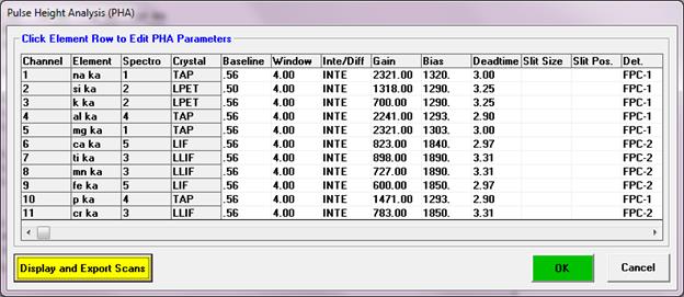
If the proper microprobe interface support is present for detector control, the detector slit size, slit position and mode (usually FPC or SPC) may also be specified for automatic control during the analysis. See the documentation on the DETECTORS.DAT file in the Configuration Files section above.
The PHA parameters dialog provides buttons to both set (write) PHA parameters to the microprobe and get (read) the PHA parameters from the microprobe (if the necessary hardware interface is available).
Note that if a gain and bias hardware interface is available, and the bias (detector high voltage) values on a given spectrometer are different for multiple elements, the acquisition will pause for two seconds before proceeding with the acquisition. For this reason the program will warn the user if the bias values are different between elements on a single spectrometer.
In addition a graphical PHA, Bias and Gain scan distribution may be acquired, based on the PHA count time and intervals specified on a single spectrometers at a time (for acquisition of all spectrometers simultaneously see the PHA window in the StartWin program). For the PHA scans, the program will measure the x-ray intensity as the baseline is varied from its current value up to the maximum baseline value with a window width based on the differential between the baseline and window and the number of points to be acquired.
For the Bias
and Gain scans the baseline and window values are set to the Scan Baseline and
Scan Window values while the bias or gain is scanned between the low and high
range values. For bias scans the gain is set to the values displayed in the
normal gain fields and for gain scans the bias is set to the value displayed in
the normal bias fields.
Note that since JEOL instruments are limited to
specific gain values, the gain values can only be modified using the spin
buttons and the gain scanning fields and button are disabled.
The PHA settings can be adjusted using a fixed bias or a fixed gain. Normally JEOL users fix the gain (since they are limited to specific gain values) and scan the bias to find the proper adjustment. Cameca users usually fix the bias to a value above the plateau level for stable response (lower energy x-rays require more bias, see below for more details) and scan the gain to determine the proper values.
Setting the bias above the "plateau" will provide the most stable count intensities since any small changes in the bias will not cause a change in the detector count rate. In this case the gain of the PHA amplifier is adjusted to place the PHA distribution is the approximate center of the amplifier range. If the argon escape peak is close to the signal peak, the gain should be adjusted so that the escape peak is either completely included or completely excluded from the PHA distribution.