Imaging
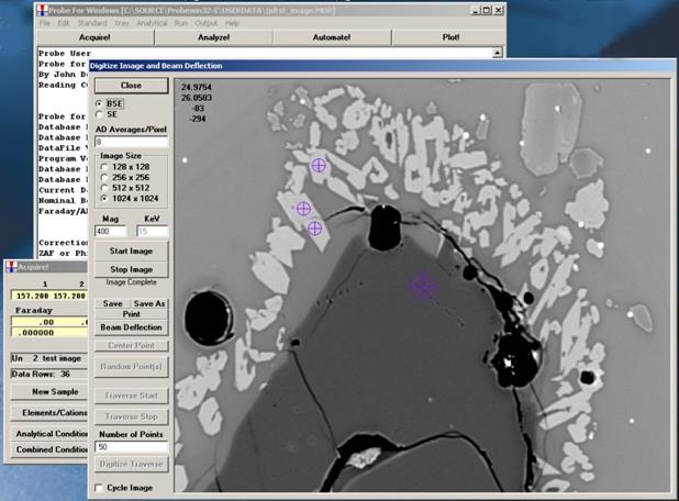
The Imaging acquisition window is very similar to the Digitize Image dialog available from the Digitize window except that it does not allow the user to digitize stage coordinates based on the image. However, it does allow the user to acquire images manually and save them to the probe database. These images are referenced to the current sample and any data point coordinates associated with that sample can be subsequently displayed using the Display Images dialog available from the Run menu. Multiple images can be saved to a single sample.

Note that the image data is 32 bit and is stored in a separate binary file from the probe database but with the same name and a .BIM extension. All images are saved as un-normalized intensities. The file format is extremely simple and consists entirely of long (4 byte) integers. The first 8 bytes are the X and Y pixel dimensions of the image and the following X by Y 4 byte values are the image data. This is repeated for each subsequent image.
Note that there are three magnifications defined in Probe for EPMA: a default magnification which is used for normal operation of the instrument between acquisitions, an analytical magnification which is used to acquire standards, unknowns and wavescans and an imaging magnification which is used to acquire images or for use with beam deflection acquisitions.
In addition, the window allows the user to manually deflect the beam using the mouse and then acquire data points at those beam deflection positions. The data point coordinates are recorded for those beam deflection positions in stage coordinates and can be displayed in the Display Image dialog available from the Run menu.
Note on the scan speed field:
ImageInterfaceType = 4 ‘ JEOL 8900/8200/8500/8x30
"AD Averages/Pixel"
Specify the number of A-D conversions to average per pixel (range 1 - 1000)
ImageInterfaceType = 5 ' SX100/SXFive mapping
“mSec/Pixel”
Specify the image dwell time in msec/pixel (range 1 - 1000)
ImageInterfaceType = 6 ' SX100/SXFive Video
“Scan Rate”
Specify the image scan speed (range = 1 - 7)
The large cross hair displayed on the image represents the beam deflection position and the smaller cross hair represents the stage position. Use the beam deflection button to deflect the beam and the Move Stage button to move the stage to the image position. The yellow color indicates the whether the window is in beam deflection or stage move mode.
 Image Calibration