[Hardware]
InterfaceType=0
NumberOfTunableSpecs=5
NumberOfStageMotors=3
JoystickXPolarity=0
JoystickYPolarity=1
JoystickZPolarity=0
SpecBacklashFlag=0
StageBacklashFlag=0
SpecBacklashType=1
StageBacklashType=1
FilamentStandbyPresent=0
FilamentStandbyType=0
FilamentStandbyExternalScript=””
EDSSpectraInterfacePresent=0
EDSSpectraInterfaceType=0
EDSThinWindowPresent=0
EDSInsertRetractPresent=0
EDSMaxEnergyThroughputPresent=0
EDSMCSInputsPresent=0
EDS_IPAddress=""
EDS_ServicePort=""
EDS_ServerName="Local Server"
EDS_LoginName="edx"
EDS_LoginPassword="edx"
WDS_IPAddress=""
WDS_IPAddress2=""
WDS_ServicePort=0
WDS_ServicePort2=0
DriverLoggingLevel=0
JeolMonitorInterval=400
JeolEOSInterfaceType=1
JeolEIKSVersionNumber=4
ThermalFieldEmissionPresent=0
LAB6FieldEmissionPresent=0
OperatingVoltagePresent=0
OperatingVoltageType=0
OperatingVoltageTolerance=0.002
BeamCurrentPresent=0
BeamCurrentType=0
BeamCurrentTolerance=0.02
BeamCurrentToleranceSet=0.01
BeamSizePresent=0
BeamSizeType=0
BeamModePresent=0
BeamModeType=1
MagnificationPresent=0
MagnificationType=1
ColumnConditionPresent=0
ColumnConditionType=0
ColumnConditionMethod=0
ColumnConditionString=""
Jeol8900PreAcquireString="" ; use commas to separate multiple commands
Jeol8900PostAcquireString="" ; use commas to separate multiple commands
AutoFocusPresent=0
AutoFocusType=0 ; 0 = parabolic, 1 = Gaussian, 2 = maximum value
AutoFocusOffset=0
AutoFocusMaxDeviation=30
AutoFocusThresholdFraction=0.33
AutoFocusMinimumPtoB=1.4
AutoFocusRangeFineScan=100 ; 50-1000 points
AutoFocusRangeCoarseScan=600
AutoFocusTimeFineScan=20 ; 1-500 msec
AutoFocusTimeCoarseScan=20
ROMPeakingPresent=0
ROMPeakingType=0 ; 0 = internal, 1 = parabolic, 2 = maxima, 3 = Gaussian
ROMPeakingParabolicThresholdFraction=0.33
ROMPeakingMaximaThresholdFraction=0.50
ROMPeakingGaussianThresholdFraction=0.33
ROMPeakingMaxDeviation=20.
AlwaysPollFaradayCupState=0
ScanRotationPresent=0
ScanRotation=0.0
DetectorSlitSizePresent=0
DetectorSlitSizeType=0
DetectorSlitPositionPresent=0
DetectorSlitPositionType=0
DetectorModePresent=0
DetectorModeType=0
MoveAllStageMotorsHardwarePresent=0
JeolCondenserCoarseCalibrationSettingLow=25
JeolCondenserCoarseCalibrationSettingMedium=35
JeolCondenserCoarseCalibrationSettingHigh=45
JeolCondenserFineCalibrationSetting=128
JeolCondenserCoarseCalibrationMode=0
JeolCondenserCoarseCalibrationBeamLow=30.4
JeolCondenserCoarseCalibrationBeamMedium=7.3
JeolCondenserCoarseCalibrationBeamHigh=1.68
JeolCondenserNumberOfApertures=1
JeolCoarseCondenserCalibrationDelay=0.1
SampleExchangePositionX=44.5
SampleExchangePositionY=1
SampleExchangePositionZ=11
SampleExchangePositionW=1
ReflectedLightIntensity=63
TransmittedLightIntensity=63
DisableSpectrometerNumber=0
SpectrometerROMScanMode=0 ; SX100/SXFive only, 0 = absolute scan, 1 = relative scan
FilamentWarmUpInterval=2.0
TurnOffSEDetectorBeforeAcquisition=0
AutomationOverheadPerAnalysis=10.0
ReflectedLightPresent=0
TransmittedLightPresent=0
HysteresisPresent=0
SX100MoveSpectroMilliSecDelayBefore=100
SX100MoveSpectroMilliSecDelayAfter=10
SX100MoveStageMilliSecDelayBefore=100
SX100MoveStageMilliSecDelayAfter=10
SX100ScanSpectroMilliSecDelayBefore=200
SX100ScanSpectroMilliSecDelayAfter=200
SX100FlipCrystalMilliSecDelayBefore=200
SX100FlipCrystalMilliSecDelayAfter=200
MinMagWindow=40
MaxMagWindow=12000000
ImageShiftPresent=0
ImageShiftType=0
CLSpectraInterfacePresent=0
CLSpectraInterfaceType=0
CLInterfaceInsertRetractPresent=0
ThermoNSSVersionNumber=”3.0”
MoveStageToleranceX=0.1
MoveStageToleranceY=0.1
MoveStageToleranceZ=0.1
InsertFaradayDuringStageJogFlag=0
InterfaceType=0
Specify the hardware interface type to be used for microprobe interface control. The following values are allowed :
0 = Demonstration mode (no hardware interface)
1 = Unused WDS
2 = JEOL 8900/8200/8500/8230/8530 interface
3 = Unused WDS
4 = Unused WDS
5 = Cameca SX100/SXFive interface
Note that specifying the wrong hardware interface could cause the computer to "lock-up" if the hardware interface defined is not actually present so be sure to consider the proper interface. The default value is 0 for demonstration mode (no hardware interface) and is always a safe mode.
You may receive a “Function Level Timeout in Driver” error message when you attempt to connect to the JEOL instrument for one of the following reasons:
1. Any component of the TCP/IP communication is not set up correctly or has been broken after setup, this includes:
a. Ethernet cable from the Probe for EPMA PC is not connected to the Ethernet switch (also Ethernet cable from switch to JEOL SC board is not connected)
b. Power to Ethernet switch is not on.
c. IP address on Probe for EPMA computer is not properly set (should be manual IP assignment, no gateway, no DNS).
2. JEOL driver DLL file is not present in expected location on the Probe for EPMA PC.
3. TCP/IP communications from the JEOL SC board, EOS board, EDS board, and OS-9 computer have been interrupted. This lack of activity can be observed on the Ethernet switch. If interrupted the normal fix is to recycle OPE power. On JEOL 8500 systems the fix is to restart SC communications.
4. The JEOL software can be used to attempt to restart the monitor between the SUN/HP and the SC board. This is accessed from the JEOL Menu - Connect EPMA System. This is sometimes successful but if all the JEOL boards have been interrupted OPE power cycle is necessary.
Cycling OPE Power ("white switch") should be done by the
microprobe operator. The switch is located on the back of the 8900 console or on
the front of the 8200 column (same for 8500).
Special note: when using InterfaceType=5 (Cameca SX100/SXFive direct socket interface), the spectrometer dynamic offsets should always be zero. Therefore, use of the Cameca Verify Spectrometers or SXLocal "veri spec" commands are discouraged, to ensure that the recorded spectrometer positions are in absolute spectrometer values.
That is to say that the Cameca Verify Spectrometer command may be used, but the multi-peak spectrometer calibration feature will not provide an accurate calibration of the theoretical spectrometer offsets since all spectrometer positions will be relative, not absolute. However, the use of the Stage verify command is perfectly fine.
NumberOfTunableSpecs=5
Enter the actual number of tunable spectrometers (scanning) on the microprobe. The allowable range is 0 to MAXTUNABLE%. The default is 0 for no tunable spectrometers.
NumberOfStageMotors=3
Enter the actual number of stage motors on the microprobe. For no stage control enter 0, for X and Y motion only, enter 2, for X, Y and Z motion, enter 3. The allowable range is 1 to MAXAXES%. The default value is 0 for no stage motors.
JoyStickXPolarity=0
The joystick X axis polarity. Applied to the X axis on the joystick to reverse the default direction of the motor. Change this value to "1" to reverse the polarity of the X axis joystick axis. The default value is 0.
Note: Joystick polarity values are used to set the Move window spin button stage polarity even if a joystick is not used in the system.
JoyStickYPolarity=0
The joystick Y axis polarity. Applied to the Y axis on the joystick to reverse the default direction of the motor. Change this value to "1" to reverse the polarity of the Y axis joystick axis. The default value is 0.
Note: Joystick polarity values are used to set the Move window spin button stage polarity even if a joystick is not used in the system.
JoyStickZPolarity=0
The joystick Z axis polarity. Applied to the Z axis on the joystick to reverse the default direction of the motor. Change this value to "1" to reverse the polarity of the Z axis joystick axis. The default value is 0. This parameter applies to 3-D joysticks only.
Note: Joystick polarity values are used to set the Move window spin button stage polarity even if a joystick is not used in the system.
JeolEOSInterfaceType=1
This parameter is used only for the JEOL instruments using the TCP/IP direct socket interface (InterfaceType = 2). Values from 1 to 3 are valid. The default is 1 for the 8200. The reason for this parameter is that the EOS (Electron Optics System) uses a different TCP/IP packet structure for the 8200/8500 and 8230/8530 compared to the older 8900 packet structure.
JeolEOSInterfaceType = 1, ThermalFieldEmissionPresent = 0 8200
JeolEOSInterfaceType = 1, ThermalFieldEmissionPresent = 1 8500
JeolEOSInterfaceType = 2 8900 (TFE flag not applicable)
JeolEOSInterfaceType = 3, ThermalFieldEmissionPresent = 0 8230
JeolEOSInterfaceType = 3, ThermalFieldEmissionPresent = 1 8530
Special note for the 8230/8530: All Probe for EPMA functions work only if the JEOL PC-SEM software is in Observation mode. Probe for EPMA returns errors for every EIKS function called if in Comparison or Analysis mode.
JeolEIKSVersionNumber=4
The JEOLEIKSVersionNumber is used by the software to indicate the current version of the JEOL EIKS interface. Use 3 for the original JEOL EIKS (2009), use 4 or 5 for the JEOL EIKS 2012. The default is 4. You can download the latest JEOL EIKS client software from our ftp site.
[hardware] JEOLEIKSVersionNumber=3
Read mag
Set mag
Read hv
Set hv
[hardware] JEOLEIKSVersionNumber=4
Read beam size
Set beam size
Read probe scan (on/off)
Set probe scan (on/off)
[hardware] JEOLEIKSVersionNumber=5
Calibrate beam current (read condenser lenses)
Set beam current (set condenser lenses)
Read "sampling mode" spot vs. scan
Set "sampling mode" spot vs. scan
Read beam deflection position
Set beam deflection position
Read optical light (reflected/transmitted
Set optical light (reflected/transmitted
Set Analog channel (SE, BSE, etc.)
ThermalFieldEmissionPresent=0
This parameter determines whether a thermal field emission gun is present. This parameter only affects the JEOL 8200/8500 and 8230/8530 and Cameca SXFive instruments at the present time. The allowable values are 0 for not present and non-zero for present. The default is zero for not present.
LAB6FieldEmissionPresent=0
This parameter determines whether a LaB6 emission gun is present. This parameter is only valid for Cameca instruments at the present time. The allowable values are 0 for not present and non-zero for present. The default is zero for not present.
This parameter is used to specify the default spectrometer backlash mode for all spectrometer motion. Enter 0 for false or any non-zero value for true. The default is 0 for no spectrometer backlash.
StageBacklashFlag=0
This parameter is used to specify the default stage backlash mode for stage motion from the Move dialog.
To set stage backlash options for standards, unknowns and wavescans separately for when the automation is used, refer to the Acquisition Options button in the Acquire! dialog. Note that the StageBacklashFlag in the Move dialog overrides the backlash options in the Acquisition Options dialog.
Enter 0 for false or any non-zero value for true. The default is 0 for no stage backlash.
SpecBacklashType=1
This parameter is used to indicate the spectrometer backlash type. Specify 1 for Probe for EPMA to control the spectrometer backlash, or 2 for ROM based backlash. The software backlash values are specified in the MOTORS.DAT file, line 7. The hardware ROM option is only available for certain hardware interfaces that support machine based automatic backlash or jog options (JEOL).
For JEOL 8900/8200/8500 instruments, this flag will enable the JEOL spectrometer backlash parameters. The actual backlash values are read from the MOTORS.DAT file, line 21 because the JEOL read backlash values command does not function properly. If the JEOL backlash values are changed in the JEOL software, be sure that the MOTORS.DAT values are also edited if it is desired that they be the same for both software packages.
StageBacklashType=1
This parameter is used to indicate the stage backlash type. Specify 1 for Probe for EPMA to control the stage backlash, or 2 for ROM based backlash. The software backlash values are specified in the MOTORS.DAT file, line 7. The hardware ROM option is only available for certain hardware interfaces that support machine based automatic backlash or jog options (JEOL).
For JEOL 8900/8200/8500 instruments, this flag will enable the JEOL stage backlash parameters. The actual backlash values are read from the MOTORS.DAT file, line 21 because the JEOL read backlash values command does not function properly. If the JEOL backlash values are changed in the JEOL software, be sure that the MOTORS.DAT values are also edited if it is desired that they be the same for both software packages.
FilamentStandbyPresent=0
This parameter is used to specify whether the microprobe hardware interface supports a filament standby mode for turning the filament off using the software automation. Enter 0 for false or any non-zero value for true. The default is 0 for no filament standby hardware interface.
FilamentStandbyType=0
The filament standby type for tungsten instruments (ThermalFieldEmissionPresent=0). The default is zero to just reduce the heat to the standby level. To reduce the heat AND turn off the HV, set FilamentStandbyType = 1. To only reduce the HV but leave the heat on (LaB6 filaments), set FilamentStandbyType = 2. To run an external script, set FilamentStandbyType = 3.
If the instrument is a JEOL 8530 the FilamentStandbyType has no effect, and this feature will simply close the gun valve (V1) in filament standby mode (ON) and open the gun valve in filament standby mode (OFF)- assuming the specimen vacuum is within the allowable range.
FilamentStandbyExternalScript=””
The name of the external script to be run if the FileamentStandbyType = 3. This can be any executable, e.g., .exe, .bat, etc. The full path to the external script must be specified, e.g., “C:\UserData\Shutdown.bat”.
EDSSpectraInterfacePresent=0
This parameter defines whether a "spectrum" EDS interface is present. This EDS spectrum interface acquires a complete EDS spectrum for each analysis and saves it to the current probe database. This way the user may change or add the elements to analyze by EDS at any time, even in off-line mode.
Note that this spectral interface automatically acquires EDS spectrum for standard samples as well as unknown samples since the full net intensity calculation and matrix correction is performed in Probe for EPMA. Enter 0 for false or any non-zero value for true. The default is 0 for no EDS spectrum interface.
EDSSpectraInterfaceType=0
The EDS spectrum interface type. This interface acquires a full spectrum for each acquisition and stores it in the probe database for subsequent processing. Unlike the above EDS “weight percent” interface, the user does not have to pre-define the elements to be acquired by EDS. Note that EDS spectrum acquisition is required for standards containing the element of interest for EDS quantification. The following low level (full spectrum acquisition) EDS interfaces are supported:
EDSSpectraInterfaceType = 0 ' Demonstration EDS spectrum mode
EDSSpectraInterfaceType = 1 ' Unused EDS
EDSSpectraInterfaceType = 2 ' Bruker RTIFCCLIENT spectrum interface
EDSSpectraInterfaceType = 3 ' Oxford Aztec spectrum interface (not supported yet)
EDSSpectraInterfaceType = 4 ' Unused EDS
EDSSpectraInterfaceType = 5 ' Thermo NSS TEPortal spectrum interface
EDSSpectraInterfaceType = 6 ' JEOL OEM spectrum interface
Note that the Thermo NSS interface requires the TEPortal.Dll and Socketdll.Dll files to be copied to the PROBE application folder (or a folder in the system path such as System32 or SysWOW64). These files can be found in the Thermo application folders in the TEPortal folder under Program Files\Thermo Scientific\NSS.
Note that the Bruker RTIFCCLIENT interface requires the RTIFCCLIENT.DLL file to be copied to the PROBE application folder. Contact Probe Software if it is not available.
EDSThinWindowPresent=0
If an ultra-thin window is used in the EDS system and combined EDS-WDS analyses are being performed, the optical light source must be turned off. This parameter is used to specify that an ultra-thin window is present that could transmit some of the optical light signal. Enter 0 for false or any non-zero value for true. The default is 0 for no EDS thin window.
EDSInsertRetractPresent=0
EDSMaxEnergyThroughputPresent=0
EDSMCSInputsPresent=0
This keyword indicates if the EDS detector hardware supports automatic insertion and retraction. The default is 0 for not present. Change to a non-zero value to indicate the insert/retract hardware is present.
The next keyword indicates that the maximum energy scale and pulse processing time is read/write. The default is 0 for not present. Change to a non-zero value to indicate the set/get max energy and pulse processing throughput hardware is present.
The EDSMCSInputsPresent keyword is used to set the WDS multi-channel spectrometer inputs for the proper element, x-ray and crystal in the Thermo or Bruker software, if the MCS hardware is present. Change to a non-zero value to indicate the MCS WDS inputs channel hardware is present.
EDS_IPAddress=""
For certain EDS interfaces the IP address of the PC EDS acquisition server must be specified. The address must be in the correct TCP/IP "dot" format, e.g. "90.0.0.3
If the EDS software server is installed on the same computer as the Probe for EPMA software, use the loopback address of 127.0.0.1. If the EDS software is installed on another computer, the IP number will be the IP address of the remote computer.
The default for the EDS_IPAddress is no IP number. This value is only used by the Thermo and JEOL EDS spectrum interfaces.
EDS_ServicePort=""
For certain EDS interfaces the service port number of the acquisition server must be specified. The service port number must be an integer between 1 and 32768. This number is used only by the JEOL OEM EDS interface (must be 5000). This number is not used by the Thermo or Bruker EDS servers (in Thermo it is specified in the application Service section (default = 5800 decimal), for Bruker it is specified in the Client remote server configuration).
EDS_ServerName="Local Server"
Used to specify the Bruker remote client server interface. If installed on the local server, the server name is usually simply “Local Server”. For remote clients, the server name must match a server defined by the Bruker Esprit client application Configuration menu (install Esprit using “Client” option).
Note that the Bruker remote server name must match exactly the server name specified in the Esprit client and is case sensitive. See the Bruker Configuration document for further details on setting up the Bruker server client for integrated EDS/WDS acquisition.
EDS_LoginName="edx"
Used to specify the Bruker remote client user. This is defined in the Bruker Esprit server application (click on the icon in the system tray). For local server interfacing the login name is usually “edx” and the password is usually “edx”.
EDS_LoginPassword="edx"
Used to specify the Bruker remote client user password. This is defined in the Bruker Esprit server application (click on the icon in the system tray). For local server interfacing the login name is usually “edx” and the password is usually “edx”.
WDS_IPAddress=""
For certain WDS interfaces (JEOL 8900, 8200 and Cameca SX100/SXFive) the IP address of the microprobe system controller must be specified. The address must be in the correct TCP/IP "dot" format, e.g. "128.32.146.11".
Note that for the JEOL 8900 and the JEOL 8200 the default IP address for the system controller is 192.6.1.11 and for the client computer it is 192.6.1.1. For the 8200, a second IP address needs to be specified for EOS (device = SEM) (see WDS_IPAddress2)
WDS_IPAddress2=""
For certain WDS interfaces (JEOL 8200) the IP address of the microprobe EOS controller must be specified. The address must be in the correct TCP/IP "dot" format, e.g. "128.32.146.11". For the JEOL 8200 this second address is the SEM EOS interface.
WDS_ServicePort=0
For certain WDS interfaces (JEOL 8900 and SX100/SXFive) the service port number of the microprobe system controller must be specified. The service port number must be an integer between 1 and 32768.
Note that for the JEOL 8900 and the JEOL 8200 the default service port number for the system controller (EPMA) must be 2785. For the JEOL 8900 only this one service port needs to be specified. For the 8200, a second service port needs to be specified (see WDS_ServicePort2)
WDS_ServicePort2=0
For certain WDS interfaces (JEOL 8200) a second service port number of the microprobe EOS controller must be specified. For the JEOL 8200 this second address is the SEM EOS interface and must be 22200. The service port number must be an integer between 1 and 32768.
Summary of JEOL parameter settings (InterfaceType = 2):
JeolEOSInterfaceType = 1, ThermalFieldEmissionPresent = 0 8200
JeolEOSInterfaceType = 1, ThermalFieldEmissionPresent = 1 8500
WDS_ServicePort = 2785, WDS_ServicePort2 = 22200
JeolEOSInterfaceType = 2 8900 (Thermal flag not applicable)
WDS_ServicePort = 2785, WDS_ServicePort2 = 2785
JeolEOSInterfaceType = 3, ThermalFieldEmissionPresent = 0 8230
JeolEOSInterfaceType = 3, ThermalFieldEmissionPresent = 1 8530
WDS_ServicePort = 22200, WDS_ServicePort2 = 22210
JeolMonitorInterval=400
Allows the user to specify the default monitor packet send interval in milli-seconds. Default is 400 msec and the minimum value is 100 msec and the maximum is 10000 msec.
OperatingVoltagePresent=0
This parameter is used to specify whether the microprobe hardware interface supports control of the accelerating voltage. Enter 0 for false or any non-zero value for true. The default is 0 for no operating voltage hardware interface.
OperatingVoltageType=0
The operating voltage hardware interface type. Not utilized.
OperatingVoltageTolerance=0
The operating voltage tolerance is used to specify how close the operating voltage read from the system must be to the desired operating voltage in order to allow the program to skip re-setting the operating voltage. The parameter is in fraction units, that is 0.01 equals 1% and the default is 0.002 or 0.2%. The allowed range is 0.0001 (0.01%) to 0.1 (10%).
BeamCurrentPresent=0
This parameter is used to specify whether the microprobe hardware interface supports control of the beam current. Enter 0 for false or any non-zero value for true. The default is 0 for no beam current hardware interface.
BeamCurrentType=0
The beam current hardware interface type. Only utilized for the JEOL 8x30 interface. 0 = normal beam current iteration method, 1 = new direct set beam current call using firmware.
BeamCurrentTolerance=0.02
The beam current tolerance is used to specify how close the beam current read from the system must be to the desired beam current in order to allow the program to skip re-setting the beam current. The parameter is in fraction units, that is 0.01 equals 1% and the default is 0.02 or 2%. The allowed range is 0.0001 (0.01%) to 0.2 (20%).
BeamCurrentToleranceSet=0.01
This is the tolerance value utilized by the JeolSetBeamCurrentMDA function to set the beam current (0.01 = 1%). This value determines how close the iteration will approach the desired beam current value. The BeamCurrentTolerance value (see above) is the tolerance value the program uses before deciding to re-set the beam current. The BeamCurrentToleranceSet value is defaulted to 0.01 and the BeamCurrentTolerance is defaulted to 0.02.
This parameter is only used by the JEOL 8200, 8900 and 8500 instruments. The BeamCurrentToleranceSet value must be less than the BeamCurrentTolerance value.
BeamSizePresent=0
This parameter is used to specify whether the microprobe hardware interface supports control of the beam size. Enter 0 for false or any non-zero value for true. The default is 0 for no beam size hardware interface.
BeamSizeType=0
The beam size hardware interface type. Not utilized.
BeamModePresent=0
This parameter is used to specify whether the microprobe hardware interface supports control of the beam scan mode. Enter 0 for false or any non-zero value for true. The default is 0 for no beam scan mode control hardware interface.
BeamModeType=1
This parameter is not currently utilized.
MagnificationPresent=0
This parameter is used to specify whether the microprobe hardware interface supports control of the scan magnification. Enter 0 for false or any non-zero value for true. The default is 0 for no beam scan magnification hardware interface.
MagnificationType=1
The beam scan magnification hardware type. This parameter is only used to specify the JEOL 6300/6400 or 8600 type magnification control (same command in both cases).
MagnificationType = 0 no magnification column control available (documentation only)
MagnificationType = 1 JEOL 6400 serial interface magnification column control
MagnificationType = 2 JEOL 8600 serial interface magnification column control
Note that if the MagnificationType = 0 the software will only use the user specified magnification for documentation purposes, for example to calibrate the scale bar of captured images from the SIS image acquisition system.
ColumnConditionPresent=0
ColumnConditionType=0
ColumnConditionMethod=0
ColumnConditionString=""
These keywords are used to specify if a column condition interface is present and if so how it should be utilized. Normally, microprobes without column interfaces use the kilovolt, beam current and beam size parameters simply for documentation purposes.
However, on instruments with a column interface, these kilovolt, beam current and beam size parameters are actually used to also set the operating condition of the electron column. On other instruments, these conditions cannot be specified individually and (or in addition), instead a "column condition string" is specified that configures the microscope for the desired operating conditions. Again, if the column condition interface is not actually present, then this field may be used simply for documentation purposes.
Some instruments, may have both the capability of setting the individual kilovolt, beam current and beam size parameters and also the capability of setting a "column condition string". In this situation either method may be used to actually set the electron column condition, however it must be noted that the even if the column condition method is utilized, the individual kilovolt (especially this parameter), beam current and beam size parameters must also be correctly specified so that the software can perform a proper quantitative matrix correction of the intensity data. This is because there is no rigorous method to determine the actual operating voltage from an arbitrary column condition string.
The ColumnConditionMethod is used to specify the default method to set the electron column operating conditions. If the ColumnConditionMethod is not specified or is zero, then the kilovolts, beam current and beam size parameters are individually specified for configuring the electron column. If the ColumnConditionMethod is 1, then the specified column condition string is utilized to set the electron column conditions.
The ColumnConditionString is used the specify the default column condition string. Normally this is blank.
AutoFocusPresent=0 ! Cameca SX100/SXFive and JEOL 8900/8200/8500/8x30 only
This parameter is used to specify whether the microprobe hardware interface supports control of the auto focus. This parameter must be set for the use of Cameca ROM based or JEOL software enabled auto focus options during automated acquisitions. Only the SX100/SXFive microprobe supports a ROM based auto focus feature, the JEOL auto-focus is software based and requires additional parameters described below. Enter 0 for false or any non-zero value for true. The default is 0 for no auto focus hardware interface. See also, the parameter EDSThinWindowPresent above.
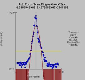
To test the JEOL autofocus use the TestType.exe program and click the Plot Last Auto Focus button to see the optical data, threshold level, parabola fit, fit coefficients, standard deviation, and calculated centroid.
AutoFocusType=0
The autofocus hardware fit method. If the parameter is zero a parabolic fit is attempted based on the thresholded light intensities. If the value is one then a Gaussian fit to all the intensity data is attempted. If the value is 2 then the software will determine the autofocus based on the maximum intensity value (this is the OEM JEOL method). The default is 2 for a maximum value fit and this parameter and most of the following auto-focus parameters applies only to the JEOL 8900/8200/8500 interface.
0 = Parabolic fit
1 = Gaussian fit
2 = Maximum value (JEOL method)
Note that in DebugMode the program will display a modeless window showing the autofocus data and fit. Click the three buttons one at a time to see the fine scan, coarse scan and 2nd fine data displayed respectively.
There is no thresholding applied to the optical data for the maximum value fit method.
AutoFocusOffset=0
The z-axis stage offset for the autofocus adjustment. Use this parameter to compensate for small but systematic offset errors in the auto-focus procedure. This parameter is added to the auto-focus Z stage position returned by the ROM based (hard coded) procedure. The value must be specified in microns and must be between –100 and +100.
Note that this value does not apply to Cameca SX100/SXFive microprobes, only JEOL 8900, 8200/8500, and 8230/8530 instruments. For setting the auto-focus offset for Cameca instruments use the OEM configuration procedure.
AutoFocusMaxDeviation=30
This is the maximum percent deviation allowed for the parabolic fit to the optical data returned from the JEOL 8200/8500, 8900, 8230/8530 ILSM command for the auto-focus procedure. If the percent deviation fit from the fine auto-focus range (+/-100um) is greater than this the procedure will issue a coarse auto-focus range (+/-500um). If this is successful a fine autofocus range is attempted using the newly found z-position.
The minimum allowed percent deviation is 1 the maximum is 60 and the default is 30.
AutoFocusThresholdFraction=0.33
This value specified the threshold fraction above which the optical data is fit for finding the auto-focus z-axis position for data returned from the JEOL 8200/8900 ILSM command. The default is 0.33 the allowable values are 0.01 to 0.99. For example, if the AutoFocusThresholdFraction is 0.33 then all optical signal data point values in the lower 1/3 of the (maximum – minimum) range will not be included in the centroid fit. Obviously this parameter does not apply to the AutoFocusType = 2 (maximum intensity value).
AutoFocusMinimumPtoB=1.4
This value determines whether a sufficient peak in the optical z-axis stage scan was acquired. This parameter applies only to JEOL 8900 and 8200 instruments. The default value is 1.4, the range of allowable values are from 1.05 to 10. The image below (from TestType) shows a properly acquired autofocus scan.
AutoFocusRangeFineScan=100
AutoFocusRangeCoarseScan=600
These values determine the auto-focus scan ranges for fine and coarse focus. Used only by the JEOL 8200/8900 interface. The default is 100 um for fine and 600 um for coarse. The range is 10 to 1000 um for fine and 60 to 6000 um for coarse.
AutoFocusPointsFineScan=200
AutoFocusPointsCoarseScan=100
These values determine the number of points for the auto-focus fine and coarse scan ranges. Used only by the JEOL 8200/8900 interface. The default is 200 points for the fine scan and 100 points for the coarse scan. The range is 50 to 1000 points for both the fine and coarse scan ranges.
AutoFocusTimeFineScan=20 ; 1-500 msec
AutoFocusTimeCoarseScan=20
These values determine the integration time per point for the auto-focus fine and coarse scan ranges. Used only by the JEOL 8200/8900 interface. The default is 20 msec for both the fine scan the coarse scan. The range is 1 to 500 msec for both the fine and coarse scan ranges.
ROMPeakingPresent=0
This parameter is used to specify whether the microprobe hardware interface supports control of the ROM based peak centering hardware that is internal to the microprobe. Enter 0 for false or any non-zero value for true. The default is 0 for no ROM based peak centering hardware interface. Note that following parameters are utilized for non ROM based and ROM based scans:
Non-ROM scan based
1. Wavescan: # of points, wave count time
2. Quickscan: Spectro scan speed (%), quick count time
ROM scan based
1. Wavescan: # of points, wave count time
2. Quickscan: Spectro scan speed (%), quick count time
ROMPeakingType=0
The ROM based peak center fit type. Applies only to Cameca SX100/SXFive and JEOL 8200/8900/8500 microprobes.
0 = Internal (the instrument ROM peak method which applies only to Cameca)
1 = Parabolic (spectrometer scan data is fit to a parabolic fit)
2 = Maxima (spectrometer scan data is fit to Brent’s Maxima function)
3 = Gaussian (spectrometer scan data is fit to a Gaussian fit)
4 = Dual ROM (Maxima for LIF crystals, Parabolic for other crystals)
5 = Dual ROM (Maxima for LIF and Gaussian for other crystals)
6 = Highest Intensity (using smoothed intensities)
To increase the default ROM scan width decrease the Peakscan Size (line 16) or increase the LiF Peaking Start Size (line 19) in the SCALERS.DAT file. Note that within the application, the ROM based peak scans are based on the Peaking Count Time divided by 4 and the number of Peak Scan Points. The ROM scan width is determined by the Peaking Start Size.
The internal ROM type is available only on Cameca instruments. The parabolic and maxima fits require at least 3 data points above the threshold (see below). The parabolic, Gaussian and maxima methods have a user defined threshold that can be specified in the INI file and within the program.
The default is 2 for Brent’s Maxima (inverted to obtain the minima).
ROMPeakingParabolicThresholdFraction=0.33
ROMPeakingMaximaThresholdFraction=0.50
ROMPeakingGaussianThresholdFraction=0.33
ROMPeakingMaxDeviation=20.
The ROM peaking thresholds are designed to allow the user to define the intensity values above which are used for one of the three ROM fitting methods (parabolic, maxima or Gaussian). The default is 0.33 which means that all intensity values 1/3 above the minimum to maximum intensity range are used in the fit.
Note that increasing the threshold decreases the number of points that can be fit. The parabolic and Gaussian methods require at least 4 data points. The minimum threshold is 0.1 and the maximum is 0.9.
The ROMPeakingMaxDeviation is the maximum percent deviation allowed in the ROM peak fit. It applies only to the parabolic and Gaussian fit options. The default is 20% and the minimum is 5% and the maximum is 80%.
ScanRotationPresent=0
ScanRotation=0.0
These parameters are used to indicate that a scan rotation interface is present and what the default scan rotation should be set to upon startup. The default is 0 for no scan rotation interface present and 0.0 for zero degrees default scan rotation. Any non-zero value is used to indicate that the scan rotation interface is present and any value from 0 to 360 is valid for the default scan rotation.
DetectorSlitSizePresent=1
DetectorSlitSizeType=0
DetectorSlitPositionPresent=0
DetectorSlitPositionType=0
DetectorModePresent=1
DetectorModeType=0
These parameters are used to indicate that an interface is present for various detector parameters. Specifically for slit size, slit position and detector mode. The default is 0 for no detector interface present and 0 for the interface type (not used at this time). Any non-zero value is used to indicate that the detector interface is present.
See the DETECTORS.DAT file for specific parameter values that can be specified by the user for configuring the various detector values.
MoveAllStageMotorsHardwarePresent=0
This parameter (intended for the JEOL stage control interfaces only), allows Probe for EPMA Xtreme to issue a stage move control in a single interface command. This is implemented to support interfaces that cannot move the stage motors individually. Set this value to a non-zero value to force Probe for EPMA to use a single command to move all three (or two) stage motors simultaneously.
Jeol8900PreAcquireString="" ; use commas to separate multiple commands
Jeol8900PostAcquireString="" ‘ use commas to separate multiple commands
These parameters are used by the JEOL 8900 (not the JEOL 8200) interface to set special conditions before and after the acquisition as specified by the user. For example, it might be desirable to give the command "PB OFF" before an acquisition to ensure that the beam is not scanning during the x-ray counting followed by the command "PB ON" to restore the beam scan after the acquisition is completed.
Use commas to separate multiple commands. For example, to send a PB ON and MG 4000 command the string should be “PB ON, MG 4000”.
Alternatively the user might prefer to issue a change in the magnification instead, "MG 100000" before the acquisition and "MG 40" after the acquisition. The default is "PB OFF" for the pre-acquire command string and "PB ON" for the post-acquire string, otherwise the default is blank.
AlwaysPollFaradayCupState=0
This parameter determines whether the faraday cup position is constantly polled through the interface. This applies to the “demo”, JEOL and Cameca interfaces.
DriverLoggingLevel=0
This parameter determines whether the driver (JEOL 8200/8900 and SX100/SXFive) will log debug information to a file with the name of the application and an extension of .LOG. Note that enabling driver logging will overwrite the existing PROBEWIN.LOG file that logs all errors within all PROBE applications. This only applies to the JEOL 8200/8900, and SX100/SXFive interfaces. The logging level may be set to 0 for disabled (no driver debug information logged), 1 for basic logging of driver information and 2 for detailed information. Note that enabling driver level debug information may slow down the application response slightly.
JeolCondenserCoarseCalibrationSettingLow=20
JeolCondenserCoarseCalibrationSettingMedium=35
JeolCondenserCoarseCalibrationSettingHigh=45
JeolCondenserFineCalibrationSetting=128
These parameters are for the JEOL 8900 and 89200 to calibrate the beam current setting (auto-mda). The program uses the three condenser coarse values to read the beam current and fit the log(beamcurrent) vs. condenser coarse for setting the approximate beam current. If necessary the program will iterate the condenser fine setting (starting at the specified setting) to get the value of the beam current based on the value of the BeamCurrentTolerance value.
The default values for both the JEOL 8200 and 8900 are 25, 35 and 45 and for the condenser fine calibration setting value is 128 for the 8900 and 255 for the 8200, and 511 if a thermal field emission gun is specified. See keyword ThermalFieldEmissionPresent above.
The beam current increases as the condenser lens values are lowered, however note that the JEOL 8200/8500 Condenser lens values are displayed inverted on the instrument console. Internally they are identical to the 8900.
JeolCondenserCoarseCalibrationMode=0
JeolCondenserCoarseCalibrationBeamLow=55.13
JeolCondenserCoarseCalibrationBeamMedium=7.9
JeolCondenserCoarseCalibrationBeamHigh=1.68
JeolCondenserNumberOfApertures=1
JeolCoarseCondenserCalibrationDelay=0.1
These values are used to provide a file based calibration curve for JEOL 8900 and 8200 instruments using aperture 1 through the number of apertures defined for the purpose of setting the coarse condenser lens value for initial iteration adjustment of the beam current.
Set JeolCondenserCoarseCalibrationMode to 0 for acquiring a fresh calibration curve and using the measured calibration curve within the program. To use a static calibration curve, set JeolCondenserCoarseCalibrationMode to 1 to use the JeolCondenserCoarseCalibrationBeamLow, JeolCondenserCoarseCalibrationBeamMedium and JeolCondenserCoarseCalibrationBeamHigh values from the INI file for setting the initial coarse condenser value when the program is adjusting the beam current.
Note that due to a subtle problem in the JEOL 8900 system, one should always set the JeolCondenserCoarseCalibrationMode value to 1 and define a manually measured condenser calibration curve. Or use the Calibrate Set beam Current button the Analytical Conditions dialog to automatically perform a beam current calibration. Here is a typical JEOL 8900 condenser calibration curve defined for a 2 aperture system:
JeolCondenserCoarseCalibrationMode=1
JeolCondenserCoarseCalibrationSettingLow=4,16
JeolCondenserCoarseCalibrationSettingMedium=21,30
JeolCondenserCoarseCalibrationSettingHigh=30, 40
JeolCondenserFineCalibrationSetting=128
JeolCondenserCoarseCalibrationBeamLow=197, 110.85
JeolCondenserCoarseCalibrationBeamMedium=18.61, 13.115
JeolCondenserCoarseCalibrationBeamHigh=4.33, 2.939
JeolCondenserNumberOfApertures=2
JeolCoarseCondenserCalibrationDelay=0.1
The beam current values are in nA and must correspond to the above JeolCondenserCoarseCalibrationSettingLow, JeolCondenserCoarseCalibrationSettingMedium and JeolCondenserCoarseCalibrationSettingHigh condenser lens values. Note that as the condenser lens values are decreased the beam current increases, however the displayed value for the 8200 in the HP software is inverted. The following is a typical (internal) response curve for the 8200 and 8900:
8200:
JeolCondenserCoarseCalibrationSettingLow=20, JeolCondenserCoarseCalibrationBeamLow=55.13
JeolCondenserCoarseCalibrationSettingMedium=35, JeolCondenserCoarseCalibrationBeamMedium=7.9
JeolCondenserCoarseCalibrationSettingHigh=45, JeolCondenserCoarseCalibrationBeamHigh=1.68
8900:
JeolCondenserCoarseCalibrationSettingLow=20, JeolCondenserCoarseCalibrationBeamLow=203
JeolCondenserCoarseCalibrationSettingMedium=35, JeolCondenserCoarseCalibrationBeamMedium=25.4
JeolCondenserCoarseCalibrationSettingHigh=55, JeolCondenserCoarseCalibrationBeamHigh=0.931
The allowable range of values are:
JeolCondenserCoarseCalibrationBeamLow > 0, JeolCondenserCoarseCalibrationBeamLow < 1000
JeolCondenserCoarseCalibrationBeamMedium > 0, JeolCondenserCoarseCalibrationBeamMedium < 1000
JeolCondenserCoarseCalibrationBeamHigh > 0, JeolCondenserCoarseCalibrationBeamHigh < 1000
Note: as of 09/21/2008 PROBE supports multiple apertures for the JEOL 8900/8200/8900/8500. Normally 8900 and 8200 instruments always use aperture 1 (the default). However, some 8500 instruments that are capable of high beam currents are configured to use aperture 2 as the default aperture. In cases where more than one aperture needs to be defined, simply indicate the number of apertures to be defined and add additional comma separated values on each line for each aperture.
In cases where multiple apertures are defined, the first value on each line indicates the lens setting and beam values for aperture 1 and the second value (comma separated) indicates the values for aperture 2 (and so on).
For the JEOL 8230/8530 the condenser lens values are opposite the 8900/8200. Therefore low condenser lens values correlate with low beam currents and high condenser lens values correlate with high beam current values. The following is an example of a 4 aperture calibration for a JEOL 8530:
8230/8530:
JeolCondenserCoarseCalibrationSettingLow=65,71,78,80 ; CC high current ~several hundred nA
JeolCondenserCoarseCalibrationSettingMedium=40,57,65,75 ; CC medium current ~25nA
JeolCondenserCoarseCalibrationSettingHigh=36,43,36,36 ; CC low current ~ 1nA
JeolCondenserFineCalibrationSetting=255 ; middle of fine cl range is 255 for 8530
JeolCondenserCoarseCalibrationMode= 1 ; use pre-calibrated calibration curve
JeolCondenserCoarseCalibrationBeamLow=609.9,107.71,111.71,37.85 ; low condenser value beam current
JeolCondenserCoarseCalibrationBeamMedium=13.836,10.2,10.354,14.09 ; medium condenser value beam current
JeolCondenserCoarseCalibrationBeamHigh=7.491,1.1001,.10031,.023 ; high condenser lens value beam current
JeolCondenserNumberOfApertures=4 ; number of sets of probe current calibration data expected
JeolCoarseCondenserCalibrationDelay=1.0
The JeolCoarseCondenserCalibrationDelay parameter is used to insert a small delay (between 0 and 2 seconds) during the coarse condenser calibration for lens hysterisis effects. The default is 0.1 seconds (100 msec). For 8230/8530 instruments, use a value of 1 or 2 seconds.
SampleExchangePositionX=44.5
SampleExchangePositionY=1
SampleExchangePositionZ=11
SampleExchangePositionW=1
These values define the stage position for performing a sample exchange. The values are defaulted to the above values for the JEOL (direct) interface and to X=0, Y=LoLimit, Z=0 for the Cameca SX100/SXFive.
ReflectedLightIntensity=63
TransmittedLightIntensity=63
These values define the default optical light intensities for the reflected and transmitted light optics. The default is 32 for the Cameca SX100/SXFive and 63 for the JEOL 8900/8200/850/8x30. The allowable range is 0 to 64 for the Cameca SX100/SXFive and 0 to 127 for the JEOL 8900/8200/8500/8x30.
DisableSpectrometerNumber=0
This value allows the user to specify a single spectrometer to be disabled on the instrument. This can be useful in the case of a non-functional spectrometer that is preventing the instrument from be used at all. Default is zero for no disabled spectrometer, allowable values are from zero to NumberofTunableSpecs.
SpectrometerROMScanMode=0 ; SX100/SXFive only, 0 = absolute scan, 1 = relative scan
This flag determines whether the Sx100/SXFive utilizes an absolute or relative spectrometer ROM scan function call for spectrometer scanning. 0 = absolute position (default) and 1 = relative position.
Note that the older SX100/SXFive instruments (spectro board type = “old”) only support ROM scanning from low to high spectrometer positions (otherwise the scan will start and run but no data is returned). This means that the MOTORS.DAT backlash factors MUST be negative for these older SX100 instruments. For newer SX100 instruments (spectro board type = “new”) the scan can be run in either direction (backlash factors can be negative or positive).
FilamentWarmUpInterval=2.0
This interval in seconds defines the amount of time delay between heat steps during the filament warmup. The default is 2 seconds and the allowable range is from 0.1 to 1000 seconds. This parameters applies only to the SX100/SXFive and JEOL 8900/8200 and 8500 interfaces.
TurnOffSEDetectorBeforeAcquisition=0
This flags tells the software whether to turn off the SE detector before each quantitative (standard or unknown) or qualitative (wavescan) acquisition. The default is zero to not turn off the SE detector before acquisition. Set it to one to have the program turn off the SE detector before each acquisition.
AutomationOverheadPerAnalysis=10.0
This parameter allows the user to override the default automation overhead for each single automated analysis to adjust the accuracy of the estimated automation time (e.g., for overnight runs). The default is 10 seconds and the valid range is from 0.1 seconds to 100.0 seconds.
ReflectedLightPresent=0
TransmittedLightPresent=0
These parameters specify if the reflected light optics or transmitted light optics hardware is interfaced. The default is 0 (false) for all interfaces except for the JEOL 8900/8200/8500/8x30 and Cameca SX100/SXFive interfaces where it is 1 (true).
HysteresisPresent=0
This parameter specifies whether the hardware supports a call to perform a hysteresis nulling to the objective lens. If this flag is set to a non-zero value the software will send a hysteresis command to the instrument after the beam size is set.
Currently only Cameca SX100 and SXFIVE instruments are supported.
SX100MoveSpectroMilliSecDelayBefore=100
SX100MoveSpectroMilliSecDelayAfter=10
SX100MoveStageMilliSecDelayBefore=100
SX100MoveStageMilliSecDelayAfter=10
SX100ScanSpectroMilliSecDelayBefore=200
SX100ScanSpectroMilliSecDelayAfter=200
SX100FlipCrystalMilliSecDelayBefore=200
SX100FlipCrystalMilliSecDelayAfter=200
These keywords allow the user to specify various delays before and after spectro and stage moves and before and after spectrometer ROM scans. These is apparently necessary for some Sx100/SXFive instruments that utilize the PFE software backlash feature and SXFive instruments for the ROM scanning. The symptoms are occasional “axis busy” or “task creation” errors.
The crystal flip delays are necessary for the SXFive and should be 200 millisecs.
The values might have to be increased slightly for some instruments to 200 or 300 millisecs.
MinMagWindow=40
MaxMagWindow=12000000
These keywords determine the minimum and maximum magnification available on the instrument. The default is 40/12000K for the JEOL and 63/12000K for the Cameca.
ImageShiftPresent=0
ImageShiftType=0
These keywords are used to specify if image shift hardware is supported. Default = True for JEOL 8900/8200/8500/8230/8530 and Cameca SX100/SXFive. The ImageShiftType is not currently utilized.
CLSpectraInterfacePresent=0
CLSpectraInterfaceType=0
CLInterfaceInsertRetractPresent=0
These keywords are to specify the CL spectrum acquisition interface for Probe for EPMA. To indicate a CL interface is present, change CLSpectraInterfacePresent to any non-zero number. The following CL interfaces will be supported:
0 = Demo CL
1 = Ocean Optics (OmniDrive driver)
2 = Gatan
3 = Newport
4 = Avantes (driver v. 8.3 or later)
ThermoNSSVersionNumber=”3.0”
This keyword defines the Thermo NSS application version number. Probe for EPMA needs to know this in order to ask whether you can specify an NSS project file for use as a template for EDS quantification.
With the release of Thermo PathFinder software, version 1.x of PathFinder should be considered version 5 with regard to the ThermoNSSVersionNumber keyword in the Probewin.ini file. Therefore to utilize the new beam deflection API in PathFinder from Probe for EPMA, edit the ThermoNSSVersionNumber keyword to 5.
MoveStageToleranceX=0.1
MoveStageToleranceY=0.1
MoveStageToleranceZ=0.1
These keywords define the minimum stage distance required to initiate a stage move for the X, Y and Z stage axes in microns. If the stage move for the given axis is less than the move stage tolerance (or all three for the JEOL stage), the stage axis move will not be initiated. The default is 0.1 microns for each axis.
InsertFaradayDuringStageJogFlag=0
This flag (if set to a non-zero value) instructs the software to insert the faraday cup when performing a stage jog (if it is not already inserted).