ROUTe:MONitor[:CHANnel]
Syntax
ROUTe:MONitor[:CHANnel] (@<channel>)
ROUTe:MONitor[:CHANnel]?
Description
This command selects the channel to be displayed on the front panel in the Monitor mode. Only one channel can be monitored at a time.
Used With:
34921A through 34925A Multiplexer Modules
34950A Digital I/O Module (digital input and counter channels only)
34952A Multifunction Module (digital input and totalizer channels only)
Parameters
|
Name |
Type |
Range of Values |
Default Value |
|
<channel> |
Numeric |
One channel in the form (@sccc). |
This is a required parameter |
Remarks
Channels do not have to be part of an active scan list to be monitored; however, the channel must be configured for a measurement in order to be monitored (see CONFigure and SENSe commands).
A scan always has priority over the Monitor function (see ROUTe:SCAN command).
Use the ROUTe:MONitor[:CHANnel]:ENABle command to enable monitor operations on the desired channels. Once the desired channels are configured, use the ROUTe:MONitor:STATe command to turn on the Monitor mode.
Any channel that can be "read" by the instrument can be monitored. This includes any combination of temperature, voltage, resistance, current, frequency, or period measurements on multiplexer channels. You can also monitor a digital input channel or the totalizer count on the digital modules.
Mx+B scaling and alarm limits are applied to the selected channel during a Monitor and all alarm data is stored in the alarm queue (which will be cleared if power fails).
For monitor operations using a multiplexer module, an error is generated if the internal DMM is disabled (see INSTrument:DMM[:STATe] command) or not installed in the mainframe. The internal DMM is not required for monitor operations on the digital modules.
For monitor operations using the internal DMM independent of any channels, use the ROUTe:MONitor:MODE command.
For 4-wire resistance measurements, the instrument automatically pairs channel n in Bank 1 with channel n+20 in Bank 2 (34921A, 34923A, 34925A) or n+35 (34922A, 34924A) to provide the source and sense connections. Monitor operations are not allowed on paired channels in Bank 2 while in the 4-wire mode (no error is generated).
The count on a totalizer channel is not reset when it is being monitored (the Monitor ignores the totalizer reset mode).
Return Format
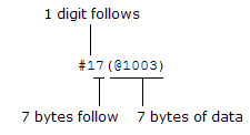
The query command returns the Monitor channel in Definite-Length Block format. The syntax is a pound sign (#) followed by a non-zero digit representing the number of characters to follow. This digit is followed by a decimal integer indicating the number of data bytes to follow. This is followed by a block of data containing the specified number of bytes. If you do not specify a channel, the channel currently displayed on the front panel is returned.
For example:

Examples
The following program segment configures channel 3 in slot 1 for dc voltage measurements, enables monitoring on the channel, and turns on the Monitor mode.
CONF:VOLT:DC (@1003)
ROUT:MON:CHAN (@1003)
ROUT:MON:CHAN:ENAB ON,(@1003)
ROUT:MON:STAT ON
The following command queries the channel currently selected as the Monitor channel.
ROUT:MON:CHAN?
Typical Response: #17(@1003)