DIAGnostic:RELay:CYCLes?
Syntax
DIAGnostic:RELay:CYCLes? (@<ch_list>)
Description
This command reads the cycle count on the specified channels. In addition to the channel relays, you can also query the count on the Analog Bus relays and bank relays.
|
|
This command reads the cycle count since it was last cleared (see DIAGnostic:RELay:CYCLes:CLEar command). The Agilent 34980A Service Guide describes how you can query the total count since the module was shipped from the factory. The factory cycle count is always available and cannot be reset. |
Used With:
34921A through 34925A Multiplexer Modules
34931A through 34934A Matrix Modules
34937A through 34939A GP Switch Modules
34941A and 34942A RF Multiplexer Modules
34945A Microwave Switch/Attenuator Driver
34946A and 34947A Microwave Switch Modules
Parameters
|
Name |
Type |
Range of Values |
Default Value |
|
<ch_list> |
Numeric |
One or more channels in the form (@sccc). |
This is a required parameter |
Remarks
The 34923A, 34924A, and 34933A modules can be configured for 2-wire (differential) or 1-wire (single ended) measurements (see SYSTem:MODule:WIRE:MODE command). Since two coils are required to drive each channel relay in the 2-wire mode, the module stores the cycle count for each coil and returns the greater of the two. To determine the cycle count for each coil, reconfigure the module for the 1-wire mode (a power cycle is required) and query the count.
In theory, the FET switches on the 34925A FET Multiplexer module have an infinite life when used under normal operating conditions. Therefore, the cycle count is not recorded and this command always returns "0" (will not generate an error). Although the count on the FET switches is not recorded, you can read the actual cycle count on the mechanical Analog Bus relays.
On the RF Multiplexer modules (34941A, 34942A), each bank consists of two leaf relays and one tree relay (see diagram below). The module stores the cycle count for each of the three relays on all four banks. The DIAGnostic:RELay:CYCLes? command returns the greater of the three values on the specified bank (i.e., reflecting the cycle count for the entire bank). Therefore, the count for Channels 101, 102, 103, and 104 will always be equal.
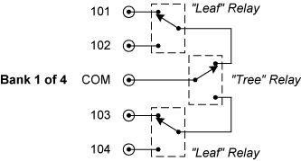
The reset state of the three relays is shown above for Bank 1 (a reset operation selects the lowest channel within the bank). The cycle count for any of the three relays is incremented whenever the relay transitions from the reset state. Therefore, the cycle count reflects a complete transition of the relay from, and back to, the reset state. For example, closing Channel 101 will not increment the leaf relay cycle count, but closing Channel 102 will increment the cycle count.
To maintain repeatable crosstalk behavior, whenever the tree relay changes position, the unconnected leaf relay will automatically return to its reset position. Note that this may result in unexpected cycle counts. For example, switching back and forth between Channels 102 and 104 will result in both leaf relay cycle counts being incremented upon each channel transition.
Obtaining relay cycle counts for the 34934A high-density matrix module is best accomplished using the 34980A web interface. To access to the web interface and view 34934A relay cycle counts:
- connect the 34980A to the PC using the LAN interface (note - the web interface is only available from the LAN)
- open a web browser and enter the 34980A IP address. To view the IP address from the front panel select:
'Utility' | 'Remote IO' | 'LAN' | 'Enable LAN' | 'View' | 'DHCP BOOT' - rotate knob
- with the 34980A web interface open, select:
> Browser Web Control (either 'Observe Only' or 'Allow Full Control' mode is ok)
> System Overview
> Module Information - select the slot containing the 34934A
> Relay Cycle Counts - all channels
> Generate Report
- the cycle count returned includes all channels of the matrix configuration and the row protection connect/disconnect and bypass relays. The row protection relays are not independently controlled but are a function of the SYSTem:MODule:ROW:PROTection command.On the 34945A Microwave Switch/Attenuator Driver, this command returns the number of times the specified coil drive has been activated.
The module will never assume that a channel is already closed/open and will always drive the channel (as long as the channel drive is not OFF; see ROUTe:RMODule:DRIVe:SOURce[:IMMediate] command).
For paired operations (see ROUTe:CHANnel:DRIVe:PAIRed[:MODE] command), the count on both the lower and upper channel in the pair will be incremented on each open/close operation.
To read the cycle count on the relays associated with function selection and isolation on the internal DMM, use the DIAGnostic:DMM:CYCLes? command.
See the Agilent 34980A Service Guide for information on replacing relays.
Return Format
The command returns the cycle count for each channel specified. The value returned is between 0 and 4,294,967,294 (32-bit value). Multiple responses are separated by commas.
Example
The following command returns the cycle count on channels 3 and 13 in slot 1.
DIAG:REL:CYCL? (@1003,1013)
Typical Response: +76289,+11055