National Instruments Interface Cards
From WinEDR
Getting Started > Laboratory Interfaces > National Instruments Interface Cards
National Instruments Inc. (www.ni.com)
WinEDR is compatible with most National Instruments multifunction data acquisition cards or devices, including M, X, and E series cards, the Lab-PC/1200 series and USB devices. The PCI-6221 PCI card (with BNC-2110 I/O box and 2m SHC68-68-EPM cable) or the USB-6221-BNC device is currently recommended.
The National Instruments NIDAQ interface library must be installed before WinEDR can use the interface card. Most modern cards (X, M and E series) are supported via the NIDAQ-MX library. Older cards (Lab-PC/1200 series) require the ‘Traditional’ NIDAQ library (V4.9 or earlier) to be installed. WinEDR supports both types of library.
Software installation
1) Install the NIDAQ library from the disks supplied with interface card, following the instructions supplied by National Instruments.
2) Install the interface card in an expansion slot (or attach a USB device).
3) Reboot the computer.
4) Run National Instruments’ Measurement & Automation Explorer program. You should find the card listed under Devices & Interfaces. Note the Device number (Dev1, Dev2 etc.) of the card.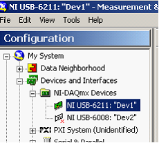
5) Right-click over the device and select Self Test to check that the device is functioning correctly.
6) If the tests check out OK, run WinEDR and select from the main menu
Setup
Laboratory Interface
to open the Laboratory Interface Setup dialog box 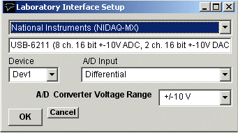
then select National Instruments (NIDAQ-MX) from the list of laboratory interface options (except for Lab-PC or 1200 series cards in which case use National Instruments (NIDAQ Trad)).
7) Select the device number of the card listed in the NI Devices & Interfaces list from the Device list (usually Dev1 if only one card is installed).
8) Set the A/D Input mode. If you are using a BNC-2110 or BNC-2090 input/output box, select Differential. (Note. The SE/DI switches on a BNC 2090 panel must be set to DI ) If you are using a Lab-PC or 1200 series card, set the A/D Input mode to Single Ended (RSE).
Signal input / output connections
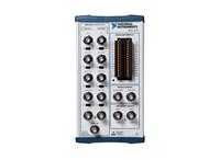
Signal input and output from National Instruments PCI cards are made via 68 pin sockets on the rear of the card attached to BNC socket input/output panels (BNC-2110 or BNC-2090 ) or screw terminal panels by appropriate shielded cables available from National Instruments.
National Instruments X, E & M Series cards
|
National Instruments X, E & M Series cards |
||
|
Analog Input |
I/O Panel |
Screw terminal panel |
|
Ch. 0 |
AI0 |
68, 67+62 (signal,ground) |
|
Ch. 1 |
AI1 |
33, 67+62 |
|
Ch. 2 |
AI2 |
65, 67+62 |
|
Ch. 3 |
AI3 |
30, 67+62 |
|
Ch. 4 |
AI4 |
28, 67+62 |
|
Ch. 5 |
AI5 |
60, 67+62 |
|
Ch. 6 |
AI6 |
25, 67+62 |
|
Ch. 7 |
AI7 |
57, 67+62 |
|
Analog Output |
|
|
|
Ch. 0 |
AO0 |
22,55 |
|
Ch. 1 |
AO1 |
21,55 |
|
Trigger Inputs |
|
|
|
Ext. Sweep Trigger |
PFI0/TRIG1 |
11,44 |
|
Ext. Stimulus Trigger |
PFI0/TRIG1 (NIDAQ-MX) |
11,44 (See Note 1) |
|
Digital Output |
|
|
|
Ch. 0 |
P0.0 |
52,53 |
|
Ch. 1 |
P0.1 |
17,53 |
|
Ch. 2 |
P0.2 |
49,53 |
|
Ch. 3 |
P0.3 |
47,53 |
|
Ch. 4 |
P0.4 |
19,53 |
|
Ch. 5 |
P0.5 |
51,53 |
|
Ch. 6 |
P0.6 |
16,53 |
|
Ch. 7 |
P0.7 |
48,53 |
Note 1. An active-high TTL pulse on this input triggers the start a stimulus program which has been set up with the External Stimulus Trigger = Y option. The trigger signal is applied to PFI0 when the NIDAQ-MX interface library is in use (Laboratory Interface Card = National Instruments (NIDAQ-MX) and PFI1 when the Traditional NIDAQ interface library (for Lab-PC/1200 cards only) is in use (Laboratory Interface Card = National Instruments (NIDAQ)
USB-6000 to USB-6005 Devices
The input/output connections for the low cost USB 6000-6005 devices are
|
USB 6000-6005 |
||
|
Analog Inputs |
Screw terminal panel |
|
|
Ch. 0 |
AI +0, -0 (signal, ground) |
|
|
Ch. 1 |
AI +1, -1 (signal, ground) |
|
|
Ch. 2 |
AI +2, -2 (signal, ground) |
|
|
Ch. 3 |
AI +3, -3 (signal, ground) |
|
|
Analog Outputs |
|
|
|
Ch. 0 |
AO 0, Gnd (signal, ground) |
|
|
Ch. 1 |
AO 1, Gnd (signal, ground) |
|
|
Trigger Inputs |
|
|
|
Ext. Sweep Trigger |
PFI0,Gnd (signal, ground) |
|
|
Ext. Stimulus Trigger |
PFI0+PFI1,Gnd (signal, ground) |
|
|
|
|
|
|
Note. |
PFI0, PFI1 and P1.0 MUST be connected together for the test pulse to generated in the Seal Test window. |
|
Lab-PC/1200 Series Cards
The input/output connections for 50 pin Lab-PC and 1200- series boards are tabulated below.
|
Lab-PC/1200 Cards |
||
|
Analog Inputs |
I/O Panel |
Screw terminal panel |
|
Ch. 0 |
ACH0 |
1,9 (signal,ground) |
|
Ch. 1 |
ACH1 |
2,9 |
|
Ch. 2 |
ACH2 |
3,9 |
|
Ch. 3 |
ACH3 |
4,9 |
|
Ch. 4 |
ACH4 |
5,9 |
|
Ch. 5 |
ACH5 |
6,9 |
|
Ch. 6 |
ACH6 |
7,9 |
|
Ch. 7 |
ACH7 |
8,9 |
|
Analog Outputs |
|
|
|
Ch. 0 |
DAC 0 |
10,11 |
|
Ch. 1 |
DAC 1 |
12,11 (See Note 1) |
|
Trigger Inputs |
|
|
|
Ext. Sweep Trigger |
EXTTRIG |
38,50 (See Note 1) |
|
Ext. Stimulus Trigger |
PB7 |
29,50 (See Note 2) |
|
Digital Synch. Input |
PC6 |
36, 13 (See Note 1) |
|
Digital Outputs |
|
|
|
Ch. 0 |
PA0 |
14,13 |
|
Ch. 1 |
PA1 |
15,13 |
|
Ch. 2 |
PA2 |
16,13 |
|
Ch. 3 |
PA3 |
17,13 |
|
Ch. 4 |
PA4 |
18,13 |
|
Ch. 5 |
PA5 |
19,13 |
|
Ch. 6 |
PA6 |
20,13 |
|
Ch. 7 |
PA7 |
21,13 |
NOTE 2 Analog output channel 1 (DAC1) is used to synchronise the start of the A/D conversion and D/A waveform generation and must be connected to EXTTRIG for WinEDR waveform generation functions to operate. In addition, if stimulus protocols containing digital ouputs are required DAC1 & EXTTRIG must also be connected to the digital synchronisation input PC6.
Note. 2. Lab-PC/1200 series boards need the pulse to be 10 ms in duration or longer.
Troubleshooting
National Instruments cards can be used with a number of different types of input/output panels ( BNC 2090, BNC 2110 or CB-68 terminal panel) and can also be configured to handle the analog input channels in a number of different ways (differential, referenced single ended and non-referenced single ended). Some combinations of settings can lead to input signals drifting or going off scale.
Differential mode (DIFF): Analog input channels are paired together and subtracted (e.g. Ch.0 – Ch.7, Ch.1 – Ch.8 etc.).
Referenced single ended mode (RSE): Analog input channels are used individually and measured relative to signal ground of the computer.
Non-referenced single ended mode (NRSE): Analog input channels are used individually and measured relative to the electrical ground of the device being measured.
When using the BNC-2110 I/O box, the USB-6221-BNC or USB-6229-BNC USB interface device the WinEDR A/D Input Mode must be set at Differential.
When using the BNC-2090 I/O box with its SE/DI switches set to DI (the default setting) the WinEDR A/D Input Mode should be set to Differential.
When using the BNC-2090 I/O box with its SE/DI switches set to SE and the RSE/NRSE switch set to NRSE the WinEDR A/D Input Mode should be set at Single Ended (NRSE)