Molecular Devices Digidata 1550/1550A/1550B
From WinEDR
Getting Started > Laboratory Interfaces > Molecular Devices Digidata 1550/1550A/1550B
Molecular Devices Corporation (www.moleculardevices.com)
The Molecular Devices Digidata 1550, 1550A and 1550B interfaces consists of self-contained, mains-powered digitiser units with BNC I/O sockets attached to the host computer via a USB 2.0 port. They support sampling rates up to 500 kHz (16 bit resolution) on up to 8 channels. They have a fixed input and output voltage range of +/-10V and support 8 analog and 8 digital output channels.
Software Installation
WinWCP uses Molecular Device's software libraries (AxDD1550.DLL, AxDD1550B.DLL or AxDD1550A.DLL) and device drivers for the Digidata 1550 Series.
1) Install the AxoScope (or PCLAMP ) software supplied with the Digidata 1550/1550A/1550B.
2) Reboot the computer.
3) Attach the Digidata interface unit to a USB port and turn it on.
4) Run WinEDR and select from the main menu
Setup > Laboratory Interface
to open the Laboratory Interface Setup dialog box.
Then select Molecular Devices Digidata 1550 if you have a Digidata 1550, Molecular Devices Digidata 1550A if you have a Digidata 1550A, or Molecular Devices Digidata 1550B if you have a Digidata 1550B from the laboratory interface list.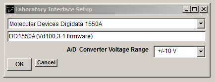
Notes.
a) The HumSilencer feature of the Digidata 1550A and B is not currently supported by WinEDR
b) When a recording is sweep manually terminated (by the user clicking the Stop button in the Record to Disk window) while WinEDR is waiting for an external START trigger pulse in the Ext Triggered recording mode, an additional trigger pulse must be applied to the Digidata START input to terminate recording.
c) Support for analog input channel re-mapping (in the AI Ch. column of the Input Channels table in the Input Channels & Amplifier Setup dialog box) is limited. Recording channels can only be remapped to HIGHER analog input numbers.
Signal input / output connections
Signal input and output connections are made via the BNC sockets on the front of the Digidata 1440A digitiser unit.
|
Digidata 1440A |
||
|
Analog Input |
I/O Panel |
Notes |
|
Ch. 0 |
Analog Input 0 |
|
|
Ch. 1 |
Analog Input 1 |
|
|
Ch. 2 |
Analog Input 2 |
|
|
Ch. 3 |
Analog Input 3 |
|
|
Ch. 4 |
Analog Input 4 |
|
|
Ch. 5 |
Analog Input 5 |
|
|
Ch. 6 |
Analog Input 6 |
|
|
Ch. 7 |
Analog Input 7 |
|
|
Analog Output |
|
|
|
Ch. 0 |
Analog Out 0 |
|
|
Ch. 1 |
Analog Out 1 |
|
|
Ch. 2 |
Analog Out 2 |
|
|
Ch. 3 |
Analog Out 3 |
|
|
Trigger Inputs |
|
|
|
Ext. Sweep Trigger |
Start |
|
|
Ext. Stimulus Trigger |
Start |
See Note 1 |
|
Digital Output |
|
|
|
Ch. 0 |
Digital Output 0 |
|
|
Ch. 1 |
Digital Output 1 |
|
|
Ch. 2 |
Digital Output 2 |
|
|
Ch. 3 |
Digital Output 3 |
|
|
Ch. 4 |
Digital Output 4 |
|
|
Ch. 5 |
Digital Output 5 |
|
|
Ch. 6 |
Digital Output 6 |
|
|
Ch. 7 |
Digital Output 7 |
|
Note 1. An active-high TTL pulse on this input triggers the start of a stimulus program which has been set up with the External Stimulus Trigger = Y option.