Adding Stimulus Waveforms to the Protocol
From WinEDR
Recording Experimental Signals > Creating Stimulus Protocols > Adding Stimulus Waveforms to the Protocol
Select the Stimulus tab page to add stimulus waveforms to the analog or digital output channels.
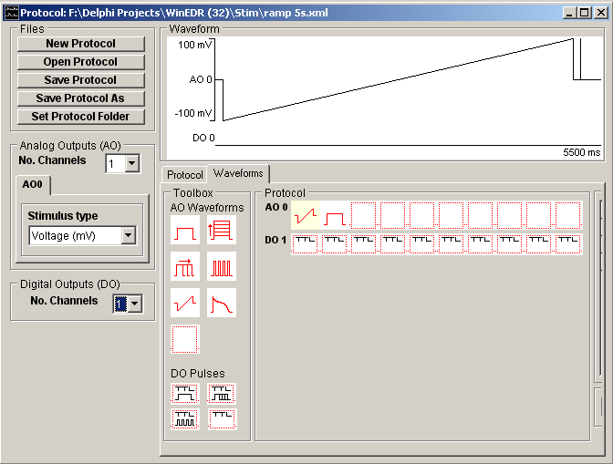
Waveforms are constructed by dragging waveform step and ramp elements from the Toolbox and dropping them into the selected voltage channel (AO 0 - AO 4) or digital (DO 0 – DO 7) output list. A plot of the resulting stimulus protocol for each output channel is shown in the protocol display panel.
A stimulus waveform on each output channel can consist of up 10 separate elements. The amplitude and duration for each element is defined in its parameters table which can be made to appear by clicking on the element.
Eight analog and 4 digital waveform elements are available in the toolbox, as detailed below.
Rectangular voltage pulse of fixed size
![]() A simple pulse, which does not vary in amplitude and duration between records. This element can be used to provide series of stimuli of fixed size or, in combination with other elements, to provide fixed pre-conditioning pulses.
A simple pulse, which does not vary in amplitude and duration between records. This element can be used to provide series of stimuli of fixed size or, in combination with other elements, to provide fixed pre-conditioning pulses.
|
|
Parameters |
|
Initial Delay |
Delay (at the holding level) before the pulse begins. |
|
Amplitude |
Pulse amplitude. |
|
Duration |
Pulse duration. |
Family of rectangular pulses varying in amplitude
![]() A rectangular voltage pulse whose amplitude is automatically incremented between recording sweeps. This element is typically used to explore the voltage-sensitivity of ionic conductances, by generating records containing the whole-cell membrane currents evoked in response to a series of voltage steps to different membrane potentials.
A rectangular voltage pulse whose amplitude is automatically incremented between recording sweeps. This element is typically used to explore the voltage-sensitivity of ionic conductances, by generating records containing the whole-cell membrane currents evoked in response to a series of voltage steps to different membrane potentials.
|
|
Parameters |
|
Initial Delay |
Delay (at the holding level) before the pulse begins. |
|
Amplitude |
Amplitude of the first pulse in the series. |
|
Amplitude (increment) |
Increment to be added to amplitude between records. |
|
Duration |
Pulse duration. |
Family of rectangular voltage pulses varying in duration
![]() A rectangular voltage pulse whose duration is automatically incremented between recording sweeps. This element is most commonly used as a variable duration preconditioning pulse in 2 or 3 step protocols for investigating inactivation kinetics of Hodgkin-Huxley type conductances.
A rectangular voltage pulse whose duration is automatically incremented between recording sweeps. This element is most commonly used as a variable duration preconditioning pulse in 2 or 3 step protocols for investigating inactivation kinetics of Hodgkin-Huxley type conductances.
|
|
Parameters |
|
Initial Delay |
Delay (at the holding level) before the pulse begins. |
|
Amplitude |
Pulse amplitude. |
|
Duration |
Pulse duration. |
|
Duration (increment) |
Increment to be added to duration between records. |
Series of rectangular voltage pulses
![]() A train of rectangular voltage pulses of fixed size. This element can be used to produce a series of stimuli to observe the effect of repeated application of a stimulus at a high rate. It can also be used to produce a train of pre-conditioning stimuli for a subsequent test waveform.
A train of rectangular voltage pulses of fixed size. This element can be used to produce a series of stimuli to observe the effect of repeated application of a stimulus at a high rate. It can also be used to produce a train of pre-conditioning stimuli for a subsequent test waveform.
|
|
Parameters |
|
Initial Delay |
Delay (at the holding level) before the pulse begins. |
|
Amplitude |
Pulse amplitude. |
|
Duration |
Pulse duration. |
|
Repeat period |
Interval between pulse in train. |
|
No. repeats |
Number of pulses in train. |
Voltage ramp
![]() A linear voltage ramp between two voltage levels. Voltage ramps provide a means of rapidly generating the steady state current-voltage relationship for an ionic conductance. (Note that, the ramp generated by the computer is not truly linear, but consists of a staircase of fine steps. These steps can be smoothed out, by low-pass filtering the voltage stimulus signal before it is fed into the patch clamp.)
A linear voltage ramp between two voltage levels. Voltage ramps provide a means of rapidly generating the steady state current-voltage relationship for an ionic conductance. (Note that, the ramp generated by the computer is not truly linear, but consists of a staircase of fine steps. These steps can be smoothed out, by low-pass filtering the voltage stimulus signal before it is fed into the patch clamp.)
|
|
Parameters |
|
Initial Delay |
Delay (at the holding level) before the pulse begins. |
|
Amplitude |
Amplitude at start of ramp. |
|
End Amplitude |
Amplitude at end of ramp. |
|
Duration |
Ramp duration. |
Digitised analog waveform
![]() A digitised analog waveform loaded from an external data file.
A digitised analog waveform loaded from an external data file.
|
|
Parameters |
|
Initial Delay |
Delay (at the holding level) before the pulse begins. |
|
File Name |
Name of text file containing digitised waveform. |
|
D/A update interval |
Time interval between digitised waveform points. |
|
No. Points |
No. of digitised waveform data points to be used in the stimulus. |
|
Starting point (increment) |
Increment to be added between records to the first data point of the digitised waveform to be used in the stimulus. |
Digitised waveforms are loaded into the stimulus protocol from text files containing the digitised data points. The waveform data can be formatted either as a single column of amplitude data or a pair of columns of time (in seconds) and amplitude (in the stimulus units of the output channel to contain the waveform) data points separated by <tab> characters, i.e.
T0 V0
T1 V1
…etc
To load a digitised waveform from a text file, click the ![]() button next to the File Name table entry and select the file containing the digitised waveform.
button next to the File Name table entry and select the file containing the digitised waveform.
After loading the data, the No. Points entry in the parameter tables indicates the number of points loaded from the file. For two column data files which contain time data the D/A update interval is set to the time difference between the first and second rows of data. For single column data files, D/A update interval must be entered by the user.
Empty analog element
![]() Empty analog waveform element. Dragging this element on to an analog output list, erases the element it is placed on.
Empty analog waveform element. Dragging this element on to an analog output list, erases the element it is placed on.
Digital pulse (fixed duration)
![]() A fixed duration digital pulse. This element can be used to switch open or close valves controlling the flow of solutions over a cell. Multiple digital outputs can be used to simultaneously open one valve while another is closed.
A fixed duration digital pulse. This element can be used to switch open or close valves controlling the flow of solutions over a cell. Multiple digital outputs can be used to simultaneously open one valve while another is closed.
|
|
Parameters |
|
Initial Delay |
Delay (at the holding level) before the pulse begins. |
|
State (0=0V,1=5V) |
Digital output state during pulse: 0=0V, 1=5V. |
|
Duration |
Pulse duration. |
Family of digital pulse (varying in duration)
![]() A digital pulse whose duration is automatically incremented between recording sweeps.
A digital pulse whose duration is automatically incremented between recording sweeps.
|
|
Parameters |
|
Initial Delay |
Delay (at the holding level) before the pulse begins. |
|
State (0=0V,1=5V) |
Digital output state during pulse: 0=0V, 1=5V. |
|
Duration |
Pulse duration. |
|
Duration (increment) |
Increment in duration between records. |
Train of digital pulses
![]() A train of digital pulses of fixed intervals and of fixed duration. This element can be used to apply a rapid train of stimuli to a cell.
A train of digital pulses of fixed intervals and of fixed duration. This element can be used to apply a rapid train of stimuli to a cell.
|
|
Parameters |
|
Initial Delay |
Delay (at the holding level) before the pulse begins. |
|
State (0=0V,1=5V) |
Digital output state during pulse: 0=0V, 1=5V. |
|
Duration |
Pulse duration. |
|
Repeat period |
Interval between pulse in train. |
|
No. repeats |
Number of pulses in train. |
Empty digital element
![]() Empty digital waveform element. Dragging this element on to a digital output list, erases the element it is placed on.
Empty digital waveform element. Dragging this element on to a digital output list, erases the element it is placed on.
D/A Update Interval
The D/A Update Interval box displays the D/A converter update interval to be used to produce the analog stimulus waveforms within the protocol.
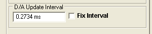
The interval is normally set to Recording Duration/No. Samples, (see Recording Settings) but may be greater than this if the laboratory interface cannot support this D/A update rate, or less if short duration pulses exist within the protocol. If digitised analog waveform elements exist within the protocol, the update interval is set to to the D/A update interval for these waveforms.
To keep the D/A update interval fixed at a specified value, enter the update interval into the D/A Update Interval box, and tick the Fix Interval option. (Note. If the laboratory interface cannot support this D/A update rate it will be adjusted to the minimum possible update interval for the interface.)