Patch/Voltage-clamp Amplifiers
From WinEDR
Getting Started > Amplifiers > Patch/Voltage-clamp Amplifiers
One of the most common WinEDR applications is recording from and controlling a whole-cell patch- or voltage-clamp experiment. Two analog channels are normally recorded by WinEDR (membrane current and voltage), and computer-generated voltage pulses are applied to the patch clamp command voltage input to stimulate the cell.
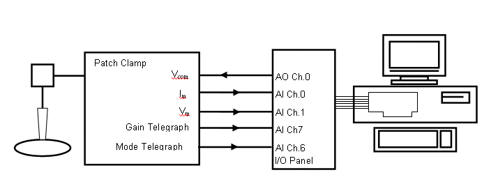 WinEDR supports up to 4 patch/voltage-clamp amplifiers and, for each amplifier in use, up to 5 analog signal connections must be made between the amplifier and laboratory interface.
A pair of laboratory interface analog input channels (designated the primary and secondary input channels) are required to record the membrane current (Im) and membrane voltage (Vm) outputs from the amplifier.
An analog output must be connected to the amplifier command voltage input (Vcom), to provide current/voltage stimulus waveforms. Two additional analog inputs may be required to receive the amplifier gain (GAIN) and voltage/current clamp mode (MODE) telegraph signals (Note. Some patch clamps do not support gain and/or mode telegraphs, others communicate gain/mode information via USB or other communications lines.)
WinEDR supports many of the commonly used models of patch- and voltage-clamp amplifiers and is able to read gain and mode telegraph signals allowing the current and voltage signal channels factors to be scaled correctly.
The required primary and secondary input channel, command voltage output, gain and mode telegraph signals connections for the amplifiers currently supported by WinEDR are shown in the table on the following page.