Cambridge Electronic Design 1401 Series
From WinEDR
Getting Started > Laboratory Interfaces > Cambridge Electronic Design 1401 Series
Cambridge Electronic Design Ltd. (www.ced.co.uk)
The CED 1401 series consists of an external microprocessor-controlled programmable laboratory interface units attached to the PC via a digital interface card or USB. There are 4 main types of CED 1401 in common use - CED 1401, CED 1401-plus, CED Micro-1401 and CED Power-1401. They are all fully supported WinEDR with the exception that only 4 analog input channels are available on the Micro1401 and that the maximum sampling rate and number of samples/sweep for the standard CED 1401 is substantially less than the others.
Software installation
Before WinEDR can use these interface units, the CED 1401 device driver (CED1401.SYS), support library (USE1432.DLL), and a number of 1401 command files stored in the directory \1401 must be installed on the computer.
The installation procedure is as following, but see CED documentation for details.
1) Install the CED interface card in a PC expansion slot and attach it to the CED 1401 via the ribbon cable supplied (or attach to USB port for USB versions).
2) Download the CED 1401 Standard Windows Installer program (WINSUPP.EXE) from the CED web site (http://www.ced.co.uk/upu.shtml) and run it to install the CED1401.SYS device driver and 1401 commands.
3) Ensure that the CED 1401 is switched on, and then reboot your computer.
4) Test the CED interface by running the program.
c:\1401\utils\try1401w.exe
and clicking the button
Run Once
5) If the tests check out OK, run WinEDR and select from the main menu
Setup/Laboratory Interface
to open the Laboratory Interface Setup dialog box.
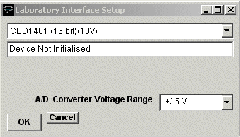
If you have a CED 1401 with standard analog ±5V output voltage range, select CED 1401 (16bit)(5V) from the list of laboratory interface options. If you have a CED 1401 with a ±10V output voltage range, select CED 1401 (16bit)(10V).
Signal input / output connections
Analog signal I/O connections are made via BNC sockets on the front panel of the CED 1401 units.
|
CED 1401 Series |
||
|
Analog Input |
I/O Panel |
Notes |
|
Ch. 0 |
ADC Input 0 |
|
|
Ch. 1 |
ADC Input 1 |
|
|
Ch. 2 |
ADC Input 2 |
|
|
Ch. 3 |
ADC Input 3 |
|
|
Ch. 4 |
ADC Input 4 |
ex. Micro1401 |
|
Ch. 5 |
ADC Input 5 |
ex. Micro1401 |
|
Ch. 6 |
ADC Input 6 |
ex. Micro1401 |
|
Ch. 7 |
ADC Input 7 |
ex. Micro1401 |
|
Analog Output |
|
|
|
Ch. 0 |
DAC Output 0 |
|
|
Ch. 1 |
DAC Output 1 |
|
|
Sync. Out |
DAC Output 2 |
CED 1401 Only (See Note 1) |
|
Trigger Inputs |
|
|
|
Ext. Sweep Trigger |
Event Input 4 Trigger In |
CED 1401, CED 1401-plus Micro 1401, Power 1401 |
|
Ext. Stimulus Trigger |
Event Input 0 |
|
|
Digital Gate I/P |
Event Input 2 |
|
|
Digital Output |
|
25 way D socket |
|
Ch. 0 |
Digital Out 8 |
17,13 (signal,ground) |
|
Ch. 1 |
Digital Out 9 |
4,13 |
|
Ch. 2 |
Digital Out 10 |
16,13 |
|
Ch. 3 |
Digital Out 11 |
3,13 |
|
Ch. 4 |
Digital Out 12 |
15,13 |
|
Ch. 5 |
Digital Out 13 |
2,13 |
|
Ch. 6 |
Digital Out 14 |
14,13 |
|
Ch. 7 |
Digital Out 15 |
1,13 |
Note.1 Standard CED 1401 Only
Events Inputs 2, 3, and 4 must be connected together and connected to DAC Output 2, to synchronise A/D sampling, D/A waveform generation and digital pulse output for WinEDR’s Seal Test option and recording with stimulus pulse protocols.
Note 2. A TTL pulse on the Ext. Sweep Trigger input triggers the start of a recording sweep when Ext Trigger sweep trigger mode has been selected.
Note 3. An active-high TTL pulse on the Ext. Stimulus Trigger input triggers the start a stimulus program which has been set up with the External Stimulus Trigger = Y option.
Troubleshooting tips
Verify that the CED 1401 is working correctly, before investigating problems using WinEDR. Use the TRY1401W program to test the CED 1401.
WinEDR uses the commands, ADCMEMI.CMD, MEMDACI.CMD and DIGTIM.CMD with the CED 1401; ADCMEM.GXC, MEMDAC.GXC and DIGTIM.GXC with the CED 1401-plus; and ADCMEM.ARM, MEMDAC.ARM and DIGTIM.ARM with the CED Micro-1401. All three commands must be available within the \1401 directory.
Power 1401
The digital pattern output command DIGTIM appears to behave differently on different versions of the Power 1401 resulting in the the digital output waveforms in a WinEDR stimulus protocol being produced incorrectly (On/Off levels are inverted and pulse durations are incorrect). This problem can be corrected by setting the CEDPOWER1401DIGTIMCOUNTSHIFT entry in the WinEDR lab interface.xml file in c:\WinEDR to 0.
Stop the WinEDR program (if it is running) and open the file c:\WinEDR\lab interface.xml with the Notepad text editor and search for the entry:
CEDPOWER1401DIGTIMCOUNTSHIFT>1</CEDPOWER1401DIGTIMCOUNTSHIFT
Change it to:
CEDPOWER1401DIGTIMCOUNTSHIFT>0</CEDPOWER1401DIGTIMCOUNTSHIFT
and save the file.
Standard CED 1401
The performance of the original CED 1401 interface unit is very limited compared to later models. The number of samples/record is limited to a total of 8192 and the achievable sampling rate when stimulus pulses are being generated is limited to a maximum of around 20 kHz divided by the number of channels.
In some circumstances, the sampling rate set by WinEDR can exceed the capabilities of the standard 1401, resulting in samples between mixed up between channels. This problem can be resolved by reducing the number of samples per record or by increasing the duration of the recording sweep.
The CED 1401 ISA card default I/O port addresses are at 300H. Check that these do not conflict with other cards within the computer. The CED 1401 also makes use of DMA channel 1 and an IRQ channel (IRQ2). These may also conflict with other cards.
Some standard 1401 appear to fail the DMA (direct memory access) test in TRY1401W and this also causes problems when running WinEDR. If this error occurs, disable the DMA channel, by clicking on the CED 1401 icon within the Windows Control Panel and un-checking the Enable DMA transfers check box.