Heka Patch Clamps & Interfaces
From WinEDR
Getting Started > Laboratory Interfaces > Heka Patch Clamps & Interfaces
Heka Electronik GmbH (www.heka.com)
The Heka EPC-9 and EPC-10 are a range of computer-controlled patch clamp amplifiers with a built-in laboratory interface unit attached to the computer via PCI interface cards or USB. Heka also supply and support the Instrutech range of laboratory interface units: ITC-16, ITC-18, ITC-1600 and their own unit the LIH-88.
Software installation
1) Install the drivers and software supplied with your patch clamp or download and install the EPC/PG drivers from http://www.heka.com/download/download.html.
2) Attach the Heka patch clamp to the computer or install the Instrutech interface card.
3) Locate the calibration files SCALE-nnnnn.EPC and CFAST-nnnnn.EPC for your EPC-9/10 patch clamp (where nnnn is your patch clamp serial number) and copy them to the WinEDR program folder (c:\program files\winEDR).
4) Run WinEDR and select from the main menu
Setup
Laboratory Interface
to open the Laboratory Interface Setup dialog box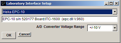
then select your device from the list (Heka EPC-10, Heka EPC-10plus, Heka EPC-10-USB, Heka EPC-9, Heka ITC-16, Heka ITC-18, Heka ITC-1600, Heka LIH-88).
5) EPC-9/10 Panel Connections: If you have an EPC-9 or EPC-10 patch clamp, connect a BNC cable between Filter 2 and A/D Input 0.
6) Instrutech ITC-16/18: I/O Panel Connections
Signal input and output connections are made via the BNC sockets on the front of the ITC-16/18 units.
|
Instrutech ITC-18 |
||
|
Analog Input |
I/O Panel |
Notes |
|
Ch. 0 |
ADC Input 0 |
|
|
Ch. 1 |
ADC Input 1 |
|
|
Ch. 2 |
ADC Input 2 |
|
|
Ch. 3 |
ADC Input 3 |
|
|
Ch. 4 |
ADC Input 4 |
|
|
Ch. 5 |
ADC Input 5 |
|
|
Ch. 6 |
ADC Input 6 |
|
|
Ch. 7 |
ADC Input 7 |
|
|
Analog Output |
|
|
|
Ch. 0 |
DAC Output 0 |
|
|
Ch. 1 |
DAC Output 1 |
|
|
Ch. 2 |
DAC Output 2 |
|
|
Ch. 3 |
DAC Output 3 |
|
|
Trigger Inputs |
|
|
|
Ext. Sweep Trigger |
Trig In |
|
|
Ext. Stimulus Trigger |
Trig In |
See Note 1 |
|
|
|
|
|
|
|
|
|
|
|
|
|
|
|
|
|
|
|
|
Note 1. An active-high TTL pulse on this input triggers the start of a stimulus program which has been set up with the External Stimulus Trigger = Y option.