Configuring AMS-2400 patch clamps
From WinEDR
Getting Started > Amplifiers > Configuring AMS-2400 patch clamps
The A-M Systems AMS-2400 patch clamps provide gain and current-/voltage-clamp operating mode information via gain and mode telegraph outputs on the rear panel of the amplifier. Up to 4 AMS-2400 patch clamps can be supported.
For each AMS-2400 in use, connections must be made between the Mode Output, Fixed Vm and Fixed Im signal output channels, Gain and Mode telegraph channels, and the analogue inputs of the laboratory interface. A connection must also be established between an analogue output and the AMS-2400 Command Input.
In voltage-clamp mode, the Mode Output channel monitors the current signal and the Fixed Vm provides the cell membrane potential. In current-clamp mode, the Mode Output switches to membrane potential and the Fixed Im output is monitored for the current. The current- voltage-clamp mode switching between the Fixed Vm and Fixed Im outputs can be accomplished either by physically changing the signal cable attachments or by reassigning analogue inputs using software.
Physically switched Secondary Input Switching
To configure WinEDR to use an AMS-2400 as Amplifier #1, select AMS-2400 as the amplifier type on the Amplifier #1 page of the Input Channels & Amplifiers Setup dialog box, as shown below.
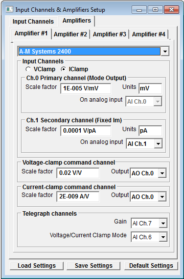
The default connections are:
|
|
Primary Ch. |
Secondary Ch. |
|
|
|
|
|
AMS-2400 |
Mode Output |
Fixed Vm |
Fixed Im |
Mode Telegraph |
Gain Telegraph |
Command Input |
|
LaboratoryInterface |
AI 0 |
AI 1 |
AI 1 |
AI 6 |
AI 7 |
AO 0 |
The secondary input channel (AI1) must be physically switched between Fixed Vm and Fixed Im when the patch clamp is switched from voltage- to current-clamp mode. This can be accomplished by physically swapping the coaxial signal cables or using a BNC switch box.
Software switched Secondary Channel Switching
Voltage/current-clamp mode switching of the Fixed Vm and Fixed Im channels can be accomplished automatically by attaching the Fixed Vm and Fixed Im outputs to different analogue input channels and remapping the analogue input to the secondary channel (Ch.1) using software.
Software channel switching can be configured by selecting the IClamp option on the Amplifier #1 page and selecting a free analogue input (e.g. AI 4) for the Ch.1 Secondary Channel, as shown below.
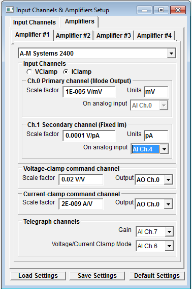
The connections for a software switched secondary channel are shown below.
|
|
Primary Ch. |
Secondary Ch. |
|
|
|
|
|
AMS-2400 |
Mode Output |
Fixed Vm |
Fixed Im |
Mode Telegraph |
Gain Telegraph |
Command Input |
|
Laboratory |
AI 0 |
AI 1 |
AI 4 |
AI 6 |
AI 7 |
AO 0 |
Multiple AMS-2400 amplifiers.
Up to three additional AMS-2400 amplifiers can be defined as Amplifiers #1-#3.
The default connections for Amplifier #2 in a two amplifier configuration are shown below
|
|
Primary Ch. |
Secondary Ch. |
|
|
|
|
|
AMS-2400 |
Mode Output |
Fixed Vm |
Fixed Im |
Mode Telegraph |
Gain Telegraph |
Command Input |
|
Laboratory |
AI 2 |
AI 3 |
AI 3 |
AI 4 |
AI 5 |
AO 1 |
This is a physically switched secondary channel configuration and assumes that Amplifier #1 is the same. To select a software switched configuration, the gain and mode telegraph channels must be moved to input channels 7-15 (if the laboratory interface supports them) or disabled by setting the Gain or Mode Telegraph settings to Off, freeing up the input channels for use as current-clamp secondary inputs.