Monitoring Input Signals & Patch Pipette Seal Test
From WinEDR
Recording Experimental Signals > Monitoring Input Signals & Patch Pipette Seal Test
You can monitor the signals appearing on each channel using the signal monitor/pipette seal test module which provides a real-time oscilloscope display and digital readout of the signal levels on the cell membrane current and voltage channels. A test pulse can also be generated for monitoring pipette resistance in patch clamp experiments.
To open the monitor/seal test module, select from the menu
RecordPipette Seal Test / Signal Monitor
An oscilloscope trace showing the current signal on each input channel is displayed.
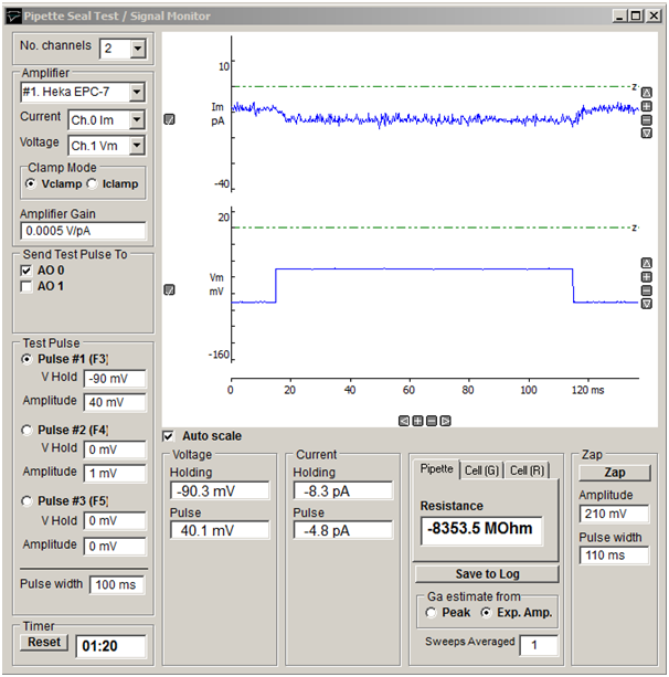
Display scaling
The vertical display magnification is automatically adjusted to maintain a visible image of the test pulse within the display area. Automatic scaling can be disabled by un-checking the Auto scale check box allowing the vertical magnification for each channel to be expanded to a selected region by moving the mouse to the upper limit of the region, pressing the left mouse button, drawing a rectangle to indicate the region and releasing the mouse button. The vertical magnification can also be adjusted using the + - buttons at the right edge of each plot.
Amplifiers
The Amplifier selection box indicates which amplifier is currently selected for seal test and the current and voltage input channels being monitored. If two or more amplifiers are in use the seal test can be switched between amplifiers by selecting Amplifier #1, #2 etc. (See Amplifiers)
The amplifier voltage/current- clamp mode is indicated by the Clamp Mode options. (When mode telegraphs are operational for the amplifier these indicate the actual state of the amplifier. When telegraph information is not available the Vclamp and Iclamp buttons must be set by the user to the amplifier clamp mode.)
The amplifier gain (current channel gain in voltage-clamp mode, voltage channel gain in current-clamp mode) is indicated in the Amplifier Gain box. When gain telegraphs are operational these indicate the actual state of the amplifier. When telegraph information is not available the current gain setting is entered here by the user.
The analog output channel(s) to which the test pulse is applied is indicated in the Send Pulse To list of check boxes. Selecting an amplifier in the Amplifier selection box, automatically selects the output channel connected to the amplifier stimulus command input. The test pulse output can be routed to a different output channel (or to additional channels) by ticking the required channels.
Cell holding voltage and test pulses
You can control the holding voltage applied to the cell and the amplitude and duration of a test voltage pulse by selecting one of three available test pulses (Pulse #1, #2, #3).
The size of each pulse type is set by entering an appropriate value for holding voltage and pulse amplitude into the Holding voltage or Amplitude box for each pulse.
The width of the pulse is defined by the Pulse width box.
You can switch between pulses by pressing the function key associated with each pulse (Pulse #1 = F3, Pulse #1 = F4, Pulse #1 = F5).
Current and voltage readouts
A readout of the cell membrane holding current and voltage, and test pulse amplitude, appears at the bottom of the monitor window.
Clicking the Save to Log button saves the current Pipette or Cell readings to the log file.
During initial formation of a giga-seal, the Pipette option displays pipette resistance, computed from

where Vpulse and Ipulse are the steady-state voltage and current pulse amplitudes. The Cell (G) page displays the cell membrane conductance, Gm, capacity, Cm, and access conductance, Ga, and the Cell (R) page displays the cell membrane resistance, Rm, (1/Gm) capacity, Cm, and access resistance, Ra, (1/Ga). Gm, Cm, and Ga are computed from
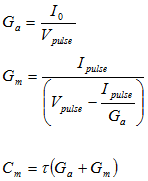
where I0 is the initial current at the start of the capacity transient and is the exponential time constant of decay of the capacitance current (See Gillis, 1995, for details). I0 ican be estimated either The Ga estimate from option determines how I0 is estimated (Peak: I0 estimated from the peak current of the capacity transient. Exp. Amp.: I0 estimated from amplitude of the fitted exponential at the start of the voltage step.
Note. If Ga, Gm and Cm are to be estimated correctly, the patch clamp’s pipette series resistance compensation and capacity current cancellation features must be turned off.
Sweeps Averaged
The Sweeps Averaged setting determines the number of test pulse sweeps averaged to calculate the displayed pipette and cell parameters (Rpipette, Rm, Gm, Cm, Ra, Ga) . Values can range from 1 (no averaging) to 10 (averaging of the 10 most recent test pulses).
Zap
Clicking the Zap button to apply a single voltage pulse of amplitude and duration defined in the Amplitude and Pulse Width boxes. A zap pulse can be used to perforate the cell membrane in a cell-attached patch to form a whole-cell path.