Closed-loop Control
Closed-loop Control
Now a simple position control is to be put into practice. Please change the circuit according to the following illustration. Please note that you need to remove the blind plug from the valve connection before you may define connections. Instead of the function generator, the displacement encoder now supplies the input voltage for the proportional valve solenoid. To define the label for the cylinder, please choose the option “Sensing” in the register “Configuration” of the properties dialog.
 Please launch
the simulation and observe how the cylinder retracts and how the
valve moves further in the closed position.
Please launch
the simulation and observe how the cylinder retracts and how the
valve moves further in the closed position.
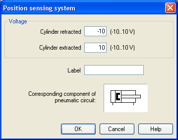
This is how the cylinder gradually becomes slower until the moment it finally and entirely retracted. Strictly speaking this does not exactly represent a position control because the cylinder would have ended its movement at the at the stop anyhow. Now we will therefore change the correlation between piston position of the cylinder and output voltage in the displacement encoder. If the cylinder is e.g. to stop in the middle, the valve needs to be exactly in closed position when the cylinder has reached this position. Since the output voltage changes proportionally to the piston position, it will be easy to calculate how the voltages at the two limits (cylinder retracted / cylinder advanced) are to be defined so that 0 volts are about at the moment of half of the cylinder stroke:
Please launch
the simulation and observe that the cylinder stops when it
reaches half of the distance.
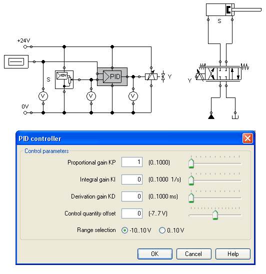
Now we wish to expand the circuit in such way that the cylinder may arrive, as rapidly as possible and still exactly, at any desired position that we define during the simulation by adjusting a controller. For this we will use a PID-controller.
Please construct
the following circuit and adjust the parameter values of the
PID-controller as indicated.
 Please note that the pump
unit and the tank, according to the above example, are situated
in reversed positions.
Please note that the pump
unit and the tank, according to the above example, are situated
in reversed positions.
Launch the
simulation and gradually change the y-offset of the function
generator between -10 and 10 .
The cylinder will travel until it has found its desired position and will stop there. The target position of the cylinder acts proportionally to the defined voltage at the function generator: -10 volts correspond to “entirely retracted”, 10 volts correspond to “entirely advanced”. The value 0 is therefore the mid-position of the cylinder piston. In the course of this the position from which the cylinder begins to travel is irrelevant, it will still stop at the desired target position.
Change the
initial piston position and observe how accurately the cylinder
reaches its target position each time.
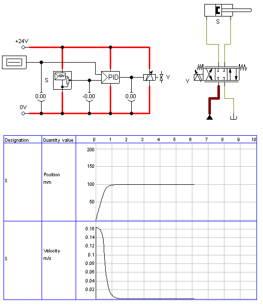
To achieve a more precise analysis of the control procedure we will observe the travel and the speed of the cylinder until it reaches its desired position. Therefore we include a state diagram, scale it to an adequate size and drag the cylinder on the diagram. A dialog will open where we choose the two state variables “Position” and “Velocity”.
Please adjust
the y-offset of the function generator to 0 and the start
position of the cylinder's piston rod to 0 and then launch the
simulation.
The cylinder travels as far as the middle and gradually decreases its speed until it stops.
It often may be desirably to make a cylinder travel by maximum speed until it reaches its desired position, and to make it stop most spontaneously. To achieve this we can amplify the position signal of the displacement encoder and therefore accelerate the reversing of the control valve. In doing so we make use of the fact that the PID-controller limits the output voltage of the proportional valve magnet to 10 volts.
Please adjust
the “proportional coefficient” of the PID-controller to 10 and
launch the simulation.

It is clear that cylinder now travels at a constant speed over a long distance. It will then be firmly slowed down and will quickly stop completely.
If instead the cylinder had
to actuate a load, it would, because of its inertia, slightly
pass the target and would need to travel back and forth a few
times until it came to rest. These vibrations around the desired
position are typical for such a basic control. In reality one
would attempt, by trimming the additional parameter of the
PID-controller or the status
controller, to cushion the vibrations.
At this point we wish to stay with the basics and would like to
draw your attention to the advanced literature on proportional
technology and control technology.