Configure Cylinders
Configure Cylinders
Double-click the cylinder to define part design, parameter and external influence of a cylinder. The status dialog of the cylinder will open.
The dialog consists of several registers, providing a convenient overview despite the vast number of settings.
Find descriptions of the dialog boxes of individual registers below.
Register “Configuration”
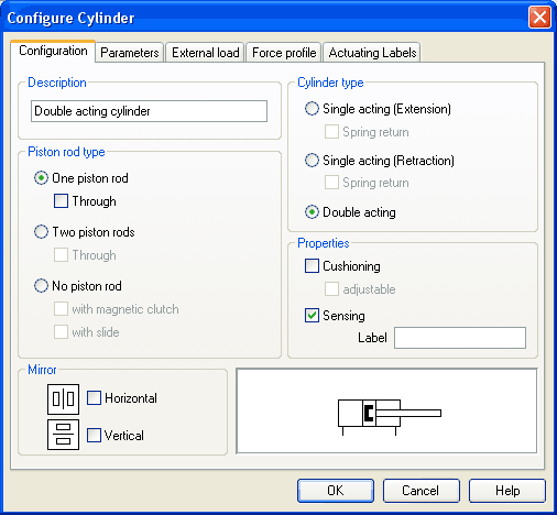
- Component DescriptionYou may enter a description for the cylinder into the text field, it will show in the state diagram and in the parts list.
- Cylinder
Type
cylinder type (single-acting, double-acting, spring return) - Piston
Rod Type
piston rod type (quantity, part design, magnet coupling, slide unit) - Properties
More properties of the cylinder (end position cushioning, sensing)
The label you may define at “sensing” serves as an interconnection with the displacement encoder. This is how, e.g. in combination with proportional valves, controlled systems can be constructed. Please find more reference to proportional technology in section Open-loop and Closed-loop Control by using Continuous Valves . - Mirror
This is where you may define whether the cylinder will be mirrored horizontally or vertically. The effect will be the same as when mirrored as in Edit- Mirror.
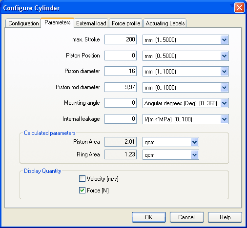
- Max.
Stroke
Maximum cylinder stroke - Piston
Position
Piston position at the start of the simulation - Piston
Diameter
Diameter of the Piston - Piston
Rod Diameter
Diameter of the piston rod of the cylinder - Mounting
Angle
The bracket affects the friction force of the moved load. You may define the mass as well as the friction coefficients in the register “external load”. - Internal
Leakage
This is where you may define the inner leakage of a cylinder. In reality there is never an ideal cylinder, since the piston never seals the chassis perfectly. Thus and despite the cut off cylinder port, the piston gradually slides under the load. - Calculated
Parameters
Piston surface and annular surface will be automatically calculated from piston diameter and piston rod diameter. - Display
Quantities
In the field “Display Quantities” you may tick state variables that are to be displayed alongside the cylinder when the “selected”-option is switched on for these state variables in the state variable box. In case in the state variable dialog box “no”-option is switched on, the particular cylinder related state variables will not be displayed.
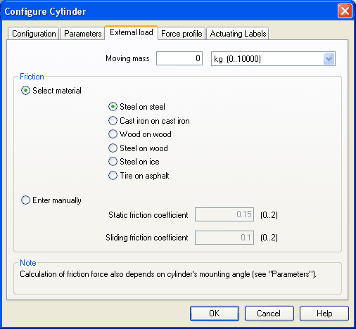
- Moving
Mass
Please enter the mass of the load here that is supposed to move cylinder. The mass of the cylinder piston and of the piston rod will be automatically and appropriately calculated by FluidSIM from the entered cylinder dimensions; thus the mass in this case refers only to the external load. Particularly, entering “0” does not conclude in the moving parts being massless. - Friction
Static friction and sliding friction determine the friction of the moving load on a surface. The internal friction inside the cylinder will be automatically and appropriately calculated by FluidSIM from the entered cylinder dimensions. Please enter “0” for both values if the load is lifted or pulled without touching a surface. In reality it is very difficult to achieve reliable values for friction. Therefore FluidSIM offers set friction coefficients for some combinations of material, providing a roundabout orientation. When comparing other tables of friction values you will notice that the (often experimentally measured) specifications differ in major ways. Please interpret these carefully and concurrently take into account the results of simulations generated by friction. Nevertheless, the variation of the friction values allows you to distinctly notice the physical influence of static and sliding friction.
Please note also that the mounting angle influences the friction force through the moved load. You may define the mounting angle in the register “parameter”.
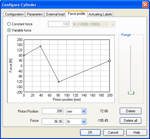
- Constant
Force
Please choose this option and enter a force if a constant force is meant to take effect for the entire distance of the cylinder movement. - Variable
Force
Please choose this option if the force changes depending on the position of the cylinder rod. You may interactively define applicable points in the chart field by clicking the mouse, these applicable points will be linked to be one lineament. Alternatively, you may mark an existing applicable point and enter the two values numerically for piston position and applicable force using the input field. - Range
Using this slider you may define the range of values to be displayed for the force. - Delete
Deletes the marked applicable point and links the two adjoining points with one straight line. - Delete
all
Deletes all applicable points and defines a constant force. Use this option to delete an existing lineament without having to delete each single applicable point.
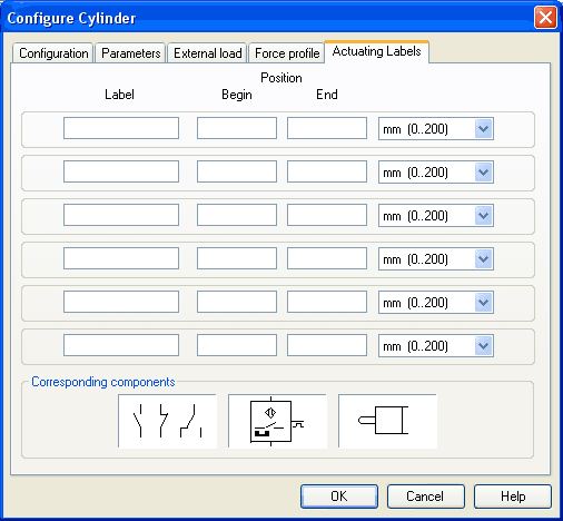
This is where you may define new actuating labels or change existing ones. This dialog box is identical to the one that is opened when you double-click on a distance rule.