DXF Import
DXF Import
Files that are of the DXF format type can be imported, retaining most of the DXF element attributes. Clearly, imported circuit diagrams or symbols cannot be simulated since the DXF standard does provide for a definition language of physical behavior models. However, the import functionality is useful if a circuit diagram shall contain elements that cannot be realized from within FluidSIM. For example, CAD drawing frames or terminal strip plans, which have been created by means of another CAD program, can be inserted into a FluidSIM drawing. Depending on whether a single symbol or a complex drawing is to be imported, particular conventions relating the grouping should be obeyed.
Having selected a DXF file via File- Open..., the dialog box for the DXF import opens.
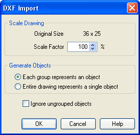
Description of the dialog box:
- Scale DrawingThe scaling factor defines scaling in percent that is applied to DXF file.
- Each
group represents an object
Enable this option if the DXF file contains several symbols. Note that symbol elements that belong together can only be identified as such, if they have been grouped within the CAD program in such a way, that the outermost group of the symbol occurs in the ENTITIES section. This means among others that no two symbols can belong to the same group. However, different symbols are allowed to share blocks; the import filter of FluidSIM creates copies for shared blocks. - Entire
drawing represents a single object
If this option is enabled, the entire drawing is treated as a single object. - Ignore
ungrouped objects
Enable this option if only for the grouped elements objects shall be generated. The elements mentioned in section ENTITIES are not considered.
If this option is disabled, FluidSIM comprises all ungrouped elements within a single object.
 If you have imported a CAD
frame, it makes sense to place this frame on a drawing layer
whose “Edit”-option is disabled: This way the frame is anchored
and will not interfere when placing components.
If you have imported a CAD
frame, it makes sense to place this frame on a drawing layer
whose “Edit”-option is disabled: This way the frame is anchored
and will not interfere when placing components.
By double clicking on an imported DXF symbol, the following dialog box is opened:
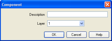
Description of the dialog box:
- Description
In this field a designation can be entered, which is also displayed in the parts list. - Layer
Defines the drawing layer of the symbol. The drawing layer is set by clicking on the down-arrow at the right-hand side of the list and selecting a layer.
Depending on the settings of drawing layer, the symbol may not be visible or may not be selectable. To display an invisible symbol or to change its properties in such a case, the drawing layer must be activated via the menu View- Layers....