Coupling Hydraulics, Electrics and Mechanics
Coupling Hydraulics, Electrics and Mechanics
In the same way FluidSIM allows you to create hydraulic circuit diagrams, the software also allows you to design electrical circuits. The components for the electrical circuits can be found in the component library and dragged from there to be inserted on the drawing area. Electrical components are connected in the same way that fluidic components are.
The following illustration shows a small example:
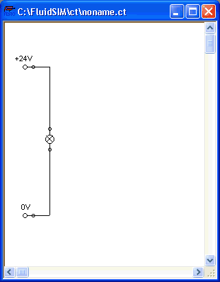
 Create this
circuit diagram on your computer.
Create this
circuit diagram on your computer.
Start the
simulation and observe that the indicator light is
illuminated.
There are also electrical components that link electrical circuits with hydraulic circuits. These linking components include switches that are hydraulically operated and solenoids that control directional valves.
Electrical circuits are drawn independently of hydraulic circuits. Therefore, there needs to be a way to create definite links between electrical components (such as a control solenoid) and hydraulic components (such as a directional valve). So-called labels bridge the difference and link both circuit diagrams together.
A label has a specific name and can be assigned to a component. If two components have the same label name they are linked together, although no apparent line is visible between them.
Entering a label takes place in a dialog box, which can be opened by either double clicking on the desired component or selecting the component and then clicking Edit- Properties.... Labels can be established on the left and right sides of an electrically operated valve by double clicking on the appropriate side, as opposed to clicking in the middle of the component.
The following example explains how labels can be used in FluidSIM.
Activate the
Edit Mode by clicking on  or Execute- Stop.
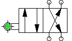
Create the
circuit diagram as shown in the following figure:
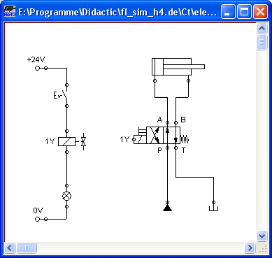
So that the valve can be controlled by the solenoid, you have to link the components with a label.
Double click on
the control solenoid or simply select the control solenoid and
click under Edit- Properties....
The following dialog box appears:
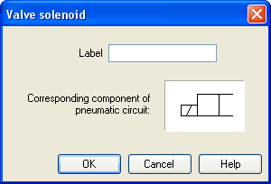
Description of the dialog box:
- Label This text field gives the label its name. A label can be up to 32 characters in length consisting of letters, numbers, and symbols.
Enter a name
for this label, for example “Y1”.
Double click on
the outside of the valve solenoid to open the dialog box for the
label name.
Input the same
label name as for the solenoid, for example “Y1”.
The solenoid is now linked to the valve.
 In practice the valve
solenoid would not be directly controlled by the switch, rather
via an intermediate relay. This component has been neglected here
for the sake of simplicity.
In practice the valve
solenoid would not be directly controlled by the switch, rather
via an intermediate relay. This component has been neglected here
for the sake of simplicity.
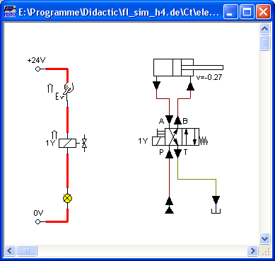
Start the
simulation.
The electrical current as well as the pressure and flow distribution are computed; the pressures are shown in color.
If you want to see the exact values of the quantities at hand, you can mark them by clicking under View- Quantity Values.... The marked quantities are displayed next to the components' connections. Section Displaying Quantity Values applies here.
Operate the
electrical switch.
As a result the valve switches and the cylinder's piston extends:
Aside from a manual or electrical operation, valves can be controlled mechanically, either through a cylinder piston or a magnet mounted at the piston. Such a coupling is realized in the same way an electrical coupling is established: By means of labels, which are assigned to the cylinder's distance rule and the mechanical valve connection.
Draw a
configurable valve on the drawing area and furnish it with a
mechanical actuator.
Double click the
mechanical actuator.
A dialog opens where a string for the related label can be entered. If the same label is assigned to the cylinder's distance rule, the valve will become actuated mechanically if the cylinder piston reaches its predefined position.
A particular form of interconnection is presented by the connection of a cylinder with a displacement encoder. This is how, e.g. in combination with proportional valves, you may create controlled systems. You will find further advice on proportional technology in section Open-loop and Closed-loop Control by using Continuous Valves .
Double-click a
cylinder.
A dialog box opens where you may define the cylinder properties. Please make sure to have the register “Configuration” in the foreground if applicable.
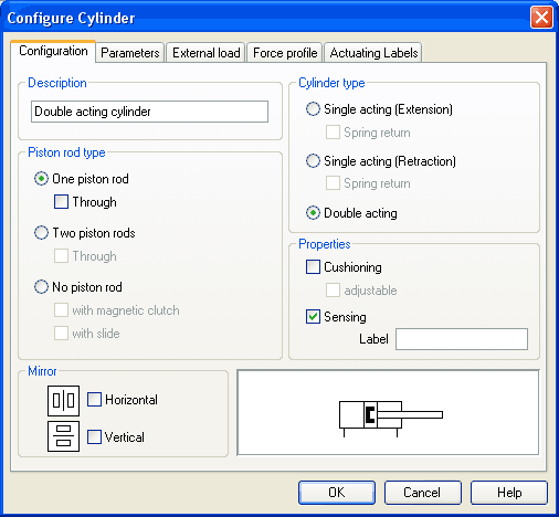
Activate the box
“Sensing” and add a label.
Insert the
displacement encoder from the component library in the circuit
and double-click to open the properties dialog. Please enter the
same label here as for the cylinder.
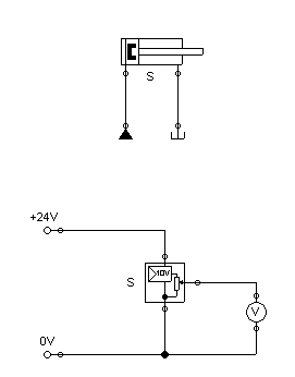
At the output the displacement encoder system provides a voltage proportional to the piston position of the interconnected cylinder. This voltage will be at its defined minimum when the cylinder is retracted completely; the voltage will be at its defined maximum when the cylinder is advanced completely.
Related Topics
Simulating Existing Circuit Diagrams
Open-loop and Closed-loop Control by using Continuous Valves