Open-loop Control
Open-loop Control
In order to understand the mode of operation of the continuous components, please reconstruct the following circuit (voltage supply, function generator, voltmeter, proportional valve solenoid, continuous valve):
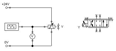
In the case of the four hydraulic connections of the valve, please don't forget to seal them by using blind plugs , to avoid warnings issued by FluidSIM.
 Please launch
the simulation and observe the continuous valve.
Please launch
the simulation and observe the continuous valve.
The function generator generates a signal between -10 and 10 volts. This varying voltage is converted in the valve by using a proportional amplifier to assign an applicable current to activate the proportional valve solenoid; converted in such way that the linked valve can be deflected to a maximum to both sides according to the applied signal voltage.
In order to be deflected less, the valve needs to have less maximum voltage. We may achieve this by double-clicking and therefore opening the properties dialog of the function generator.
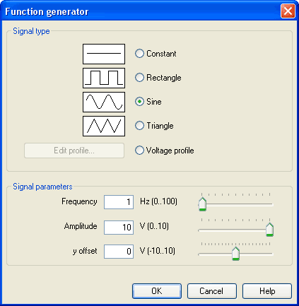
Please define 4
for an “amplitude”, close the dialog and launch the simulation
again.
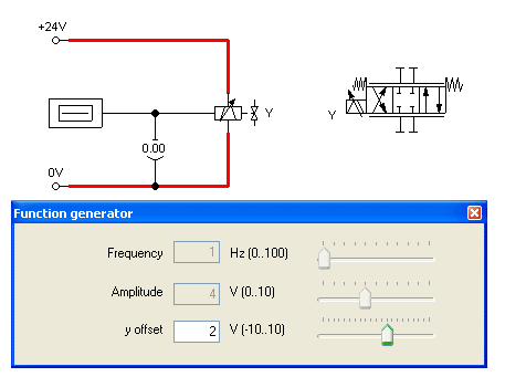
Now the voltage will alternate between -4 and 4 volt. This will still cause the valve to swing symmetrically, but it will show less deflection around the mid-position.
Please open the
properties of the function generator again and define 2 for the
y-offset.
The function generator now supplies a voltage between -2 and 6 volts, causing the valve to deflect more to the left-hand side than to the right-hand side.
Please open the
properties of the function generator and define “Constant” for a
type of signal.
 The slider of the function
generator for “Frequency” and “Amplitude” provide no function for
the type of signal “Constant”. Therefore we may model a manually
adjustable potentiometer.
The slider of the function
generator for “Frequency” and “Amplitude” provide no function for
the type of signal “Constant”. Therefore we may model a manually
adjustable potentiometer.
Please launch
the simulation and click (by a single click) on the
function generator.
A window will open showing the slider of the function generator.
Gradually change
the y-offset and observe how the valve moves subject to the
controller setting.