

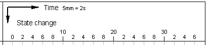
Adjust the representation of the diagrams
On the right side of a diagram row you can find the area in which the curves can be drawn.
A double-click on this area opens a corresponding dialog box. You can determine the appearance of the drawing area with it. Please make sure that there is no diagram element under the mouse like e.g. a signal element.
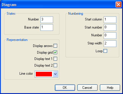
- States – NumberThe entry defines the number of states and by that the number of horizontal lines in the diagram row.
- States
– Base state
Horizontal lines through the base state are drawn with a thin pen. - Numbering – Start
column
The start column indicates at which column the numbering is to begin. - Numbering – Start
number
The start number indicates with which number the numbering is to begin. - Numbering –
Number
The number indicates how many steps are to be numbered. - Numbering – Step
width
Defines the step width between two numbers. - Numbering –
Loop
If this field is marked, an equals sign and the start number display additionally after the last number. - Representation – Display
arrows
If this field is marked, two arrows display. - Representation – Display
grid
If this field is marked, the background grid displays. - Representation – Display
text 1
If this field is marked, a text box displays. It can be used for marking purposes. This text box belongs to the row you have chosen and cannot be shifted into another row. - Representation – Display
text 2
If this field is marked, an additional text box displays. It can be used for marking purposes. This text box belongs to the row you have chosen and cannot be shifted into another row. - Representation – Line
color
Defines the color of the diagram lines.