Drawing Layers
Drawing Layers
Components in FluidSIM that cannot be simulated, such as texts, DXF import data, rectangles, circles, state diagrams, and parts lists, can be assigned to one of eight drawing layers. Each layer can be shown or hidden as well as set locked or unlocked. These properties are defined under View- Layers...; here also a layer can be given a name. Components of FluidSIM that can be simulated are always on layer 1.
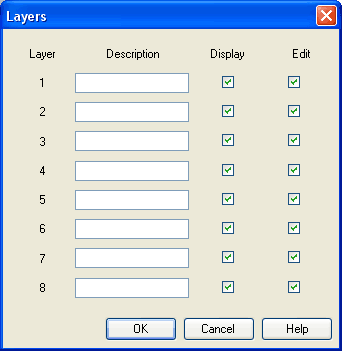
- Description The layer name is displayed in the dialog box of an object's properties instead of the layer number.
- Display
If the option “Show” is disabled, the respective drawing layer is invisible, and, of course, can not be edited. - Edit
If the option “Edit” is disabled, the respective drawing layer is still visible but cannot be edited. I.e., the objects that belong to such a locked layer can neither be selected, nor moved or deleted. By this concept e.g. a drawing frame can be protected. To edit objects on a locked layer, first unlock the layer.
 The identifiers
of components and connections in FluidSIM's standard circuit
library stand on drawing layer two. By disabling the
“Show”-option for this layer, the identifiers are made
invisible.
The identifiers
of components and connections in FluidSIM's standard circuit
library stand on drawing layer two. By disabling the
“Show”-option for this layer, the identifiers are made
invisible.