

Switches at Cylinders
Limit switches, proximity switches, and mechanically operated valves can be activated by the piston of the cylinder. Therefore, it is necessary to use a distance rule at the cylinder to position the switches correctly:
 Drag a cylinder
and a distance rule
Drag a cylinder
and a distance rule  to the drawing
area.
to the drawing
area.
Drag the
distance rule near to the cylinder.
When the distance rule is dropped near the cylinder, it automatically snaps in the right position. Move the cylinder just slightly and the distance rule moves with it. If you move the cylinder more than a centimeter in distance, the connection between distance rule and cylinder is broken, and the distance rule does not travel with.
The correct position for a distance rule depends on the type of cylinder. Distance rules can be set above the cylinder, before the cylinder (on the moving piston), or at both positions at the same time:
Double click on
the distance rule.
The following dialog box appears:
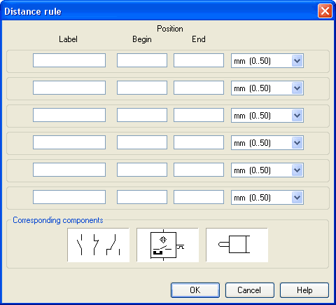
Description of the dialog box:
- Label The text insertion fields on the left are for naming labels from proximity switches or limit switches in electrical circuits, which are actuated by the movement of the cylinder's piston.
- Position
The description fields on the right-hand column define the precise begin and end positions of the switches and of the limit switch at the cylinder.
At the first line, please
enter 35 for both labels “Y1” and for begin and end position,
then please close the dialog box by clicking “OK”.
Immediately following, a mark with the appropriate label appears beneath the distance rule:
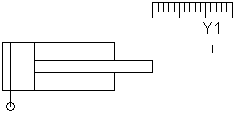
I.e., this cylinder activates the switch or the valve with the label “Y1”, when its piston has moved 35 mm, provided the switch in the electrical part of the circuit resp. the mechanical “connection” of the valve was given the same label.
Once the cylinder in the above example has exceeded the position 35 mm, the switch will be put to off. If you wish the activation of the switch to last over a longer distance, please enter the applicable begin and end positions in the dialog.
To place labels for electrical switches, please double-click the component; valves with mechanical actuation come with a particularly designed “connection”, e.g. at the end of the stem, or at the center of the roller. If the component or the connection has already got a label you may double-click the label straight away instead of the connection in order to change the designation.