Simulating Existing Circuit Diagrams
Simulating Existing Circuit Diagrams
Included with the FluidSIM installation disks are a number of working circuit diagrams.
Among others, these are circuit diagrams as part of the learning material and will be discussed in the following workbooks “Hydraulics Basic Level TP 501”, “Hydraulics Advanced Level TP 502”, “Electrohydraulics Basic Level TP 601” and “Electrohydraulics Advanced Level TP 602”.
The circuit library of the FluidSIM student version contains only circuits of the basic levels.
These circuit diagrams can be opened and simulated with FluidSIM as follows:
 Click on
 or choose
Circuit
Preview in the File menu.
or choose
Circuit
Preview in the File menu.
Preview windows containing overviews of existing circuit diagrams should appear:
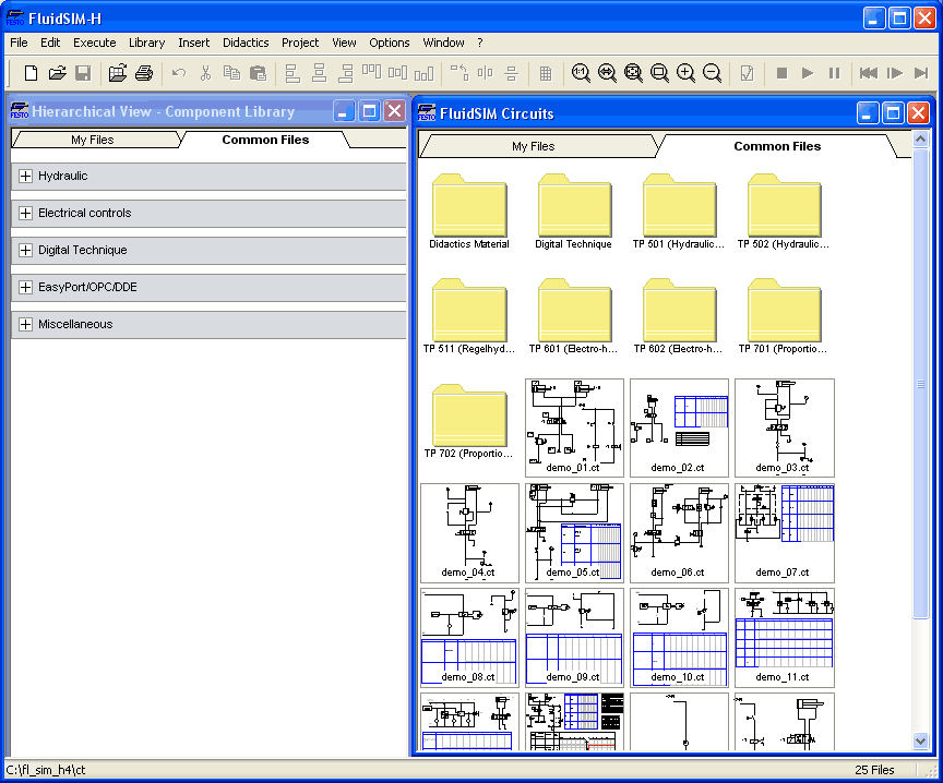
A preview window displays the circuit diagrams of a specific directory in alphabetical order accompanied by a miniature representation. The name of the current directory is shown in the title bar of the preview window; the files of the FluidSIM circuit diagrams contain the extension ct.
By double clicking a directory icon you go down to the respective subdirectory.
 In the
ct
subdirectory of
the fl_sim_h
installation
additional subdirectories for diagrams can be created. These
subdirectories are automatically found by FluidSIM, and extra
directory icons are created for them.
In the
ct
subdirectory of
the fl_sim_h
installation
additional subdirectories for diagrams can be created. These
subdirectories are automatically found by FluidSIM, and extra
directory icons are created for them.
Open the circuit
diagram demo1.ct
by double
clicking on its miniature representation.
Circuit
diagrams can also be opened using the File Selector dialog box.
By clicking on  or choosing
Open...
under
the File menu, the File Selector
dialog box will appear, in which a circuit diagram can be opened
by double clicking on its filename.
or choosing
Open...
under
the File menu, the File Selector
dialog box will appear, in which a circuit diagram can be opened
by double clicking on its filename.
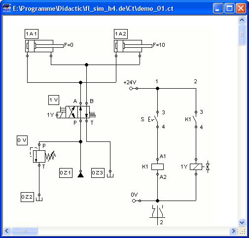
In either case the circuit diagram is opened and displayed in a new window:
Click on
 or on
Execute- Start, or press the key
F9.
or on
Execute- Start, or press the key
F9.
FluidSIM
switches to the simulation mode and starts the simulation
of the circuit diagram. When in the simulation mode, the mouse
cursor changes to a hand  .
.
During the simulation FluidSIM first calculates all electrical parameters. pressure is calculated.
This step is followed by formulating a model of the hydraulic circuit and, based on this model, a continuous distribution for flow and pressure will be calculated for the circuit.
Formulating models is demanding. Depending on a circuit's complexity and the computer's power, a circuit's simulation may take considerable time. Likewise, the real-time completion of the following dynamic simulation cannot always be guaranteed. The percentage of real-time achieved is shown in FluidSIM in the status bar at the lower edge of the main window.
As soon as the results are available, the connection lines will be shown in color and the cylinders extend in sequence:
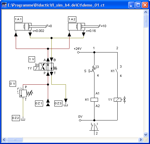
The colors of the connection lines have the following meaning:
Colors of the electrical and hydraulic lines
|
Color |
Meaning |
|
Dark red |
Hydraulic line: pressure ³ 50% of maximum |
|
Ocher |
Hydraulic line: pressure < 50% of maximum |
|
Light red |
Electrical line, current flowing |
You can define your own mapping between colors and state values under Options- Simulation.... The varying thicknesses of the dark red connection lines corresponds to the pressure as related to the maximum pressure. FluidSIM distinguishes between three thicknesses of line:
Thickness of the dark red hydraulic connection lines
|
Thickness |
Meaning |
|
|
Pressure ³ 50% and < 75% of maximum |
|
|
Pressure ³ 75% and < 90% of maximum |
|
|
Pressure ³ 90% of maximum |


The exact numeric values for pressures, flow rates, voltages, and currents are displayed on the attached measuring instruments. Section Displaying Quantity Values describes how you may go about getting values for all or only selected variables on the circuit diagram, even when measuring instruments are not present.
Simulation in FluidSIM is
based on physical models whose components match those components
found in the Festo Didactic GmbH
& Co. KG equipment set. Therefore, calculated
values should closely match measured values. When comparing
results, please acknowledge the fact that in practice,
measurements can be subject to large fluctuations. The reasons
for differences range from component tolerances to oil
temperature.
The calculation of variables forms the basis for an exact, real-time proportional animation of the cylinder.
Real-time-proportionality guarantees the following property: If in reality a cylinder moves twice as fast as another one, the relationship between these two components is shown in the animation. In other words, the real-time relationship remains unaltered.
Manually operated valves and switches, found in the circuit diagram, can be switched by clicking on them with the mouse:
Move the mouse
cursor to the left switch.
The mouse
cursor becomes a hand with index finger  and indicates that
the switch may be flipped.
and indicates that
the switch may be flipped.
Click on the
switch.
When you click on a manually operated switch, its real behavior is simulated. In this example the clicked switch becomes closed and recalculation begins automatically. Following the calculation, the new pressure and flow values are indicated and the cylinders retract.
The switching of a component
is only possible when a simulation is running
() or when a simulation has
been set to pause ( ).
).
In the event that you would like to simulate another circuit diagram, it is not necessary to close the open one. FluidSIM allows you to have several circuits open at one time. Furthermore, FluidSIM is able to simulate multiple circuits simultaneously.
Click on
 or
Execute-
Stop
to switch the
current circuit from Simulation Mode to Edit Mode.
or
Execute-
Stop
to switch the
current circuit from Simulation Mode to Edit Mode.
By switching a circuit from
Simulation Mode to Edit Mode, all components will automatically
be set back to their “normal status”. In particular, switches are
set to their original position, valves switch to their normal
position, cylinder pistons are set to their previous
position, and all values calculated are deleted.
By clicking on
(alternative:
Execute- Pause or F8) you can switch
from Edit Mode to Simulation Mode without starting the
simulation. This feature is useful, if components shall be set
before the simulation is started.
Related Topic
Additional Simulation Functions