Creating new Circuit Diagrams
Creating new Circuit Diagrams
This section contains an introduction to creating and simulating circuit diagrams using FluidSIM.
 Create an empty
drawing area by clicking on
Create an empty
drawing area by clicking on  or under
File- New to open a new
window:
or under
File- New to open a new
window:
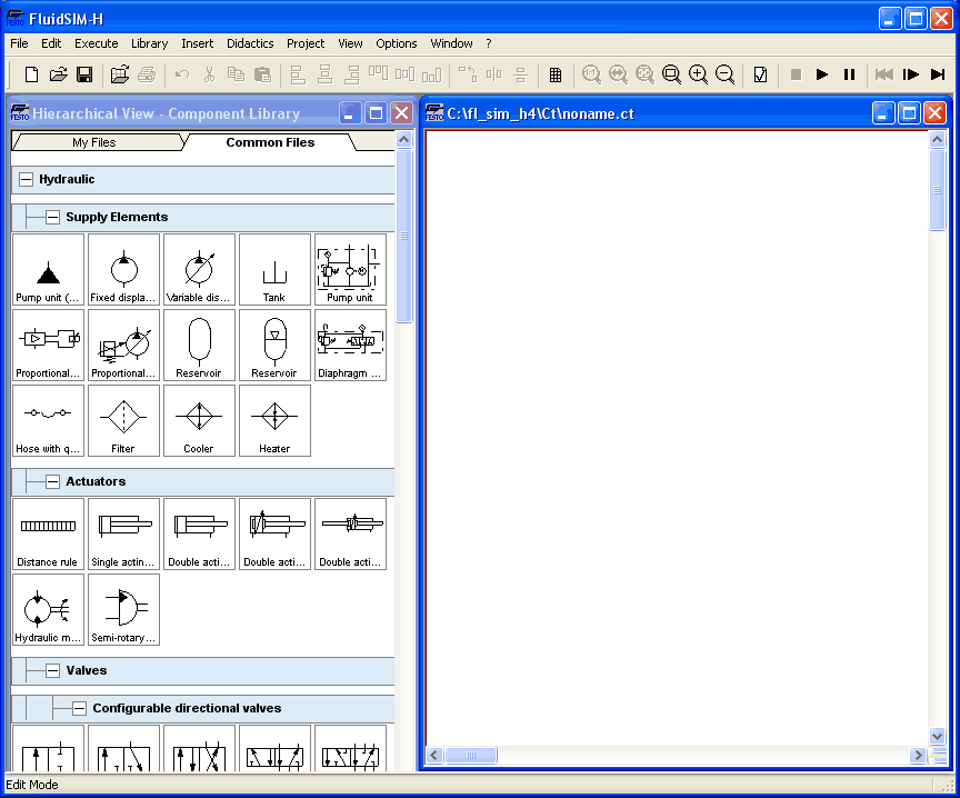
 Circuit diagrams can only be
created or altered in the Edit Mode. The Edit Mode is indicated
with the following mouse cursor
Circuit diagrams can only be
created or altered in the Edit Mode. The Edit Mode is indicated
with the following mouse cursor  .
.
Each and every newly opened drawing area automatically contains a name, with which it can be saved. This name is found in the title bar of the new window.
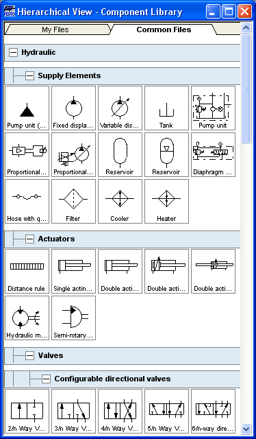
While in basic mode, you will see the available component groups in the hierarchical view of the component library. To list the components of a group, you may list off the group by clicking it. For a better overview you may also hide non-required elements and subgroups by once more clicking and hence closing the hierarchy. Component groups may often contain further subgroups that may also be listed off or closed.
To list off a group including all of its subgroups, you may hold the Shift-Key while clicking. This will reduce your efforts to list off each subgroup. You may similarly use the Shift-Key to close all subgroups of a superordinate group.
press the
Shift-Key, hold it and click “Hydraulic”.
The entire group of hydraulic components will be listed off. Using the scrollbars, you may browse through the component library to the left and right or up and down.
Using the mouse and “drag-and-drop” you may drag components from the component library to the drawing area:
Move the mouse
cursor to a component in the library, more specifically to the
cylinder.
Press the left
mouse button. While continuing to hold down the button, move the
cursor.
The cylinder is
then highlighted (selected) and the mouse cursor changes
to a four way directional cross  . The component's outline
moves with the mouse cursor.
. The component's outline
moves with the mouse cursor.
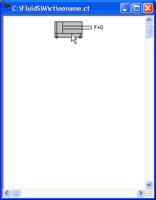
Move the cursor
to the drawing area and release the button on the mouse. This
action places the cylinder in the drawing area:
In this way it is possible to “drag” each component from the component library and place it in the desired position in the drawing area. In the same way it is possible to rearrange components already in the drawing area.
Drag the
cylinder to the bottom right hand corner.
In order to simplify the
creation of circuit diagrams, the components automatically snap
to grid in the drawing area.
Try to move the
cylinder onto a non-permissible area, for example outside the
window.
Outside a
permissible area the mouse cursor changes to the prohibited
sign  ; the component cannot be
dropped.
; the component cannot be
dropped.
Drag a second
cylinder onto the drawing area and notice that the second
cylinder is now highlighted.
Highlight, say,
select the first cylinder by clicking on it.
Delete the
cylinder by clicking on  (cut) or under
Edit- Delete or by pressing the
Del key.
(cut) or under
Edit- Delete or by pressing the
Del key.
The commands in the
Edit
menu correspond
only to the selected components.
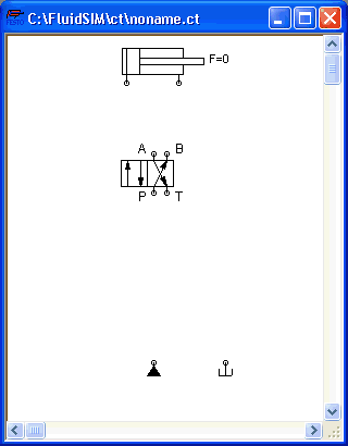
Drag onto the
drawing area a configurable 4/n-way valve, a pump unit, and a
tank.
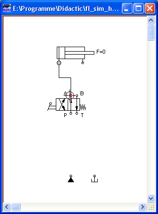
Arrange the
components in the following manner:
Double click the valve to assign an operation mode to it. A dialog box appears:
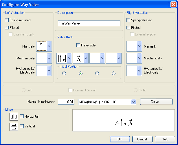
- Left/Right ActuationFor both sides the actuation modes of the valve can be defined individually; it can be one or more of the categories “Manually”, “Mechanically”, or “Hydraulically/Electrically”. An operation mode is set by clicking on the down-arrow at the right-hand side of the list and selecting a symbol. If for a category no operation mode is desired, simply choose the blank symbol from the list. Moreover, for each side of the valve the attributes “Spring-returned” and “Piloted” can be set.
- Description
Enter here a name for the valve. This name is used in the state diagram and in the parts list. - Valve
Body
A configurable valve has at most four positions. For each of the positions a valve body element can be chosen individually. Such an element is set by clicking on the down-arrow at the right-hand side of the list and selecting a symbol. If for a position no element is desired, simply choose the blank symbol from the list. The valve may be marked “Reversible” to indicate that there is no particular direction of flow. - Initial
Position
This button defines the valve's initial position (sometimes also called normal position or neutral position), which is the position without having any operation applied to the valve. Note that this setting is only exploited if it physically does not contradict a spring-returned setting, possibly defined above. - Dominant
Signal
A “Dominant signal” on the left or right-hand side defines the overriding signal, in case the valve is addressed from both sides simultaneously. - Hydraulic
Resistance
This is where you define the hydraulic resistance of the valve.
Choose from the left-hand
side in the topmost list a manual operation with snap in, and
select the “Spring-returned” option in the right field. Close the
dialog box via OK.
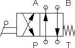
Now the valve should look as follows:
Move the mouse
cursor over the left cylinder connection .
In Edit Mode,
the mouse cursor changes to a cross-wires pointer
 , when it is above a
component connection .
, when it is above a
component connection .
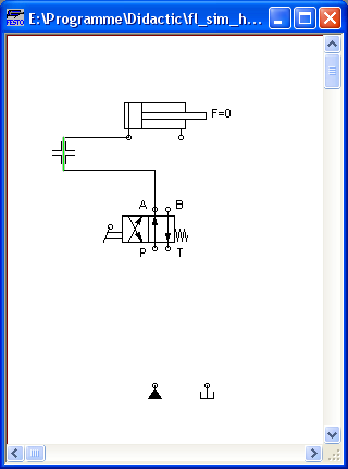
Press the left
mouse button while the mouse cursor is above the cylinder
connection. Move the mouse cursor and notice how the cross-wires
pointer gains arrows  .
.
Keep pressing
the mouse button, and move the cross-wires pointer
to the upper left
valve connection. Notice how the arrows on the cross-wires
pointer turn inward  .
.
Release the
mouse button.
Immediately a line appears between the two chosen connections:
FluidSIM
automatically draws a line between the two chosen connections.
The mouse cursor changes to the prohibited sign
when it is not
possible to draw a line between two connections.
Move the mouse
cursor to a line.
In the Edit
Mode, the mouse cursor changes to a line-selection symbol
 , when it is positioned over
a line.
, when it is positioned over
a line.
Press the left
mouse button and move the line-selection symbol to the left.
Release the mouse button.
Immediately, the line is redrawn:
In the Edit Mode the components and lines can be selected, moved, or deleted by clicking on Edit- Deleteor by pressing the Del key.
Connect the
remaining components.
The circuit diagram should look somewhat like the following one:
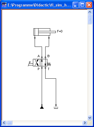
The circuit diagram has been completely drawn and connected. Attempt to simulate this circuit.
Start the
simulation by clicking on  (or under
Execute- Start or with the F9
key).
(or under
Execute- Start or with the F9
key).
During simulation all pressures and flow rates are calculated, all lines are colored, and the cylinder's piston extends.
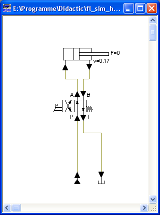
After the cylinder has been extended, the pressure in the cylinder supply line must inevitably increase. This situation is recognized by FluidSIM and the parameters are recalculated; the pressure downstream of the pump unit increases to the value, as defined by the pump unit safety guard.
In order to keep the value of the maximum pressure low, the pump unit must be equipped with a pressure relief valve.
Activate the
Edit Mode by clicking on  (or under
Execute- Stop or with the F5
key).
(or under
Execute- Stop or with the F5
key).
Drag a pressure
relief valve and a second tank into the window.
In reality, to connect a
component to an existing line requires a T-connection . FluidSIM
automatically creates a T-connection when you draw a line from a
connection to an existing line.
Using the
cross-wires cursor draw a line between
the input connection of the pressure relief valve to the line
connecting the pump unit and the valve. Notice how the arrows in
the cross-wires turn inwards .
Release the
mouse button.
The T-connection appears on the line at the point where the mouse button was released.
Connect the tank
to the pressure relief valve.
If necessary,
draw the line so that the wiring diagram is arranged
clearly.
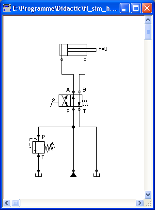
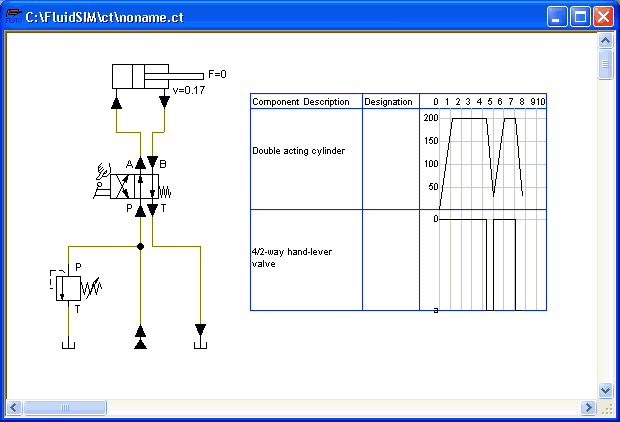
The circuit diagram should now appear somewhat like the following diagram:
Save the circuit
by clicking on  or File- Save. FluidSIM automatically
opens the File Selector dialog box, if the title is new; here you
must give the circuit a name.
or File- Save. FluidSIM automatically
opens the File Selector dialog box, if the title is new; here you
must give the circuit a name.
Start the
simulation by clicking
.
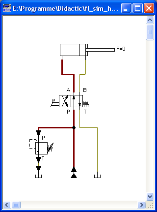
The cylinder's piston extends. As soon as the piston fully extends, a new situation arises. This situation is recognized by FluidSIM and is recalculated. The pressure relief valve opens and the distribution of pressure is shown:
FluidSIM not only animates
manually operated components during changeover, but nearly all
components with multiple states.
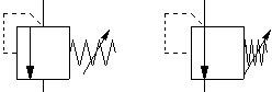
The following figure shows a pressure relief valve in closed and open position:
Recall that in the Simulation Mode, manually operated valves and switches can be switched with a mouse click:
Move the mouse
cursor over the left-hand side of the valve.
The mouse
cursor becomes a hand with an extended index finger
 and indicates that the
valve can be switched.
and indicates that the
valve can be switched.
Click on the
left side of the valve and hold the mouse button down.
When you click on a valve, the real behavior of the valve is simulated. In our example the valve is switched to crossover position and a recalculation is initiated automatically. As a result, the pressure relief valve closes and the cylinder retracts. As soon as the cylinder reaches its left stop, the pressure relief valve opens again.
Components whose switching
status is not locked remain activated as long as the mouse button
is held down.
Stop the
simulation, which also brings you to Edit Mode. Select from the
component library the state diagram component, and place it onto
the drawing area.
The state diagram records the state quantities of important components and depicts them graphically.
Move the state
diagram to a free place in the drawing. Drag the cylinder and
drop it onto the state diagram.
A dialog opens where you may choose the desired status variables. In this particular case only the position is of interest, so you may confirm the default selection by choosing OK.
Start the
simulation and observe the state diagram.
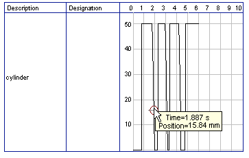
Set the
simulation to “Pause”-mode and move the mouse curser to the graph
in the diagram.
When resting on the diagram for approximately one second, the mouse curser will call a window indicating the exact values of time and of the applicable status variable. The display will move along and update the values when you move the mouse alongside the graph.
You may use several status diagrams in one window as well as you may display several components in the same diagram. By dragging a component onto the diagram you will add the component to the status diagram. A selection dialog will appear where you may choose the applicable status variables and different colors. A repeated drag onto the diagram will open the dialog again, so you may change your choice. In case no status variable of a component is selected, the component will be removed from the diagram. The following components and the applicable status variables may be displayed in the status variable diagram:
Recording state quantities in the state diagram
|
Component |
State |
|
cylinder |
position, velocity |
|
|
acceleration, force |
|
way valve |
position |
|
pressure meter, accumulator |
pressure |
|
shutoff valve and throttle valve |
opening level |
|
pump, motor |
rpm |
|
semi-rotary actuator |
position |
|
pressure valve and switching valves |
state, pressure |
|
flow control valves |
flow |
|
flow meter |
flow, volume |
|
pressure or switching valve |
state |
|
switch |
state |
|
relay, valve solenoid |
state |
|
indicator light, buzzer, pressure indicator |
state |
|
counter |
state, counter value |
|
function generator, voltmeter |
voltage |
|
status controller, PID-controller |
voltage |
The example is now finished. Further editing and simulation concepts are described in the next chapter.
Related Topic
Advanced Concepts in Simulating and Creating Circuits