Simulation Parameters
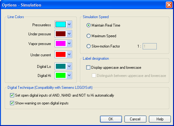
By clicking under Options- Simulation... a dialog box appears with parameters for simulation:

Description of the dialog box:
- Line ColorsDuring simulation the electrical, the hydraulic and the digital lines get colored, depending on their state. The mapping from a state to a color is set by clicking on the down-arrow at the right-hand side of the list and selecting a color.
- Maintain Real
Time
Using the option “Maintain Real Time” will attempt the cylinder movement to move as fast as in reality. Please note that real time movement requires a computer with sufficient computing power. - Maximum
Speed
The option “maximum speed” utilizes the entire computing power. The aim is to run the simulation as fast as possible. The actual acceleration of the simulation depends on the performance of the computer. If your computer does not at least achieve “real-time”, the simulation cannot be accelerated to any higher speed. - Slow-motion
Factor
The slow-motion factor controls whether the simulation should go more slowly then it would in reality. With a slow-motion factor of 1:1, the simulation should proceed in real-time. - Label
designation
By default, FluidSIM does not distinguish between uppercase and lowercase characters in label identifiers of mechanical or electrical connections. I.e., label identifiers are automatically converted to uppercase. Now, using the option “Display uppercase and lowercase”, label identifiers are treated case sensitively. Case sensitivity can be enabled for both display purposes and a more strict label identity checking. In the former case, upper- and lowercase characters, say, for instance “a” and “A”, are displayed as such, but treated as the same character. In the latter case, which is enabled by the option “Distinguish between uppercase and lowercase”, “a” and “A” are treated as different labels. - Digital
Technique (Compatibility with Siemens
LOGO!Soft)
It is a useful convention in the field of digital technology setting open input ports of AND, NAND, and NOT components to Hi. Otherwise, e.g. an AND gate with three input ports would not function as expected if only two of its input ports were connected. Many constant Hi connections may clutter up a circuit unnecessarily, and hence FluidSIM can be configured to set open input ports of the respective components always to Hi. This option can be disabled of course. If open input ports have been detected at the start of the simulation, FluidSIM issues a warning message. The display of this message can also be disabled.

