Transitions
Transitions are used to describe the sequence of a control system. To do this, add the following information to GRAFCET:
 Select “2” as
the name of the second (simple) step. The transition conditions
that specify when the system moves from one step to the next are
still missing. A transition is considered released once all the
immediately preceding steps are active. A transition is triggered
once it has been released and its condition has the value “1”. A
transition with the value “1” is displayed in green in FluidSIM.
You can show a descriptive text instead of the formula, as with
the actions.
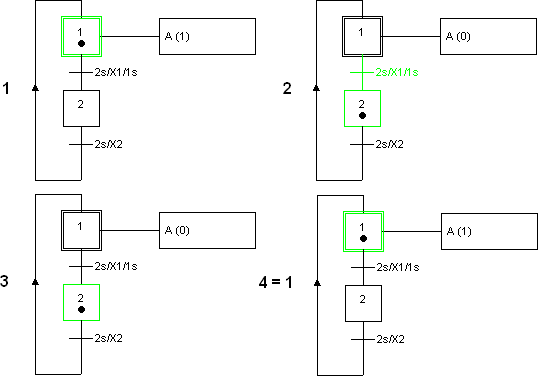
A Boolean value is automatically generated for each step. The name begins with an “X”, followed by the name of the step. In the example here, the variables “X1” and “X2” are generated. The value of a step variable is “1” if the step is active; otherwise it is “0”.
Transition conditions can be time-dependent. These have the following form:
t1 s / “term” / t2 s
Where t1 and t2 have to be replaced by numbers and “term” by a Boolean term.
The transition condition becomes true (“1”) t1 seconds after “term” has changed its value from “0” to “1”. This is called a “rising edge”. The transition condition becomes false again (“0”) t2 seconds after “term” has changed its value from “1” to “0”. This is called a “falling edge”.
The short form t1 s / “term” is also allowed. The system then assumes that t2 is 0 seconds.
 Enter the
transition conditions into the transitions' properties dialogue
as shown and then start the simulation.
The following cycle runs through:

Related Topics

