[173] Exercise: Drilling machine (pressure regulator)
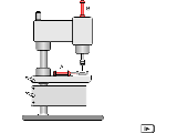
 The drill feed and clamping
device of a drilling machine are hydraulically actuated. The
hydraulic control system contains two cylinders, a clamping
cylinder 1A and a feed cylinder 2A. The clamping pressure at
cylinder 1A must be adjustable, since different workpiece
clamping forces are required. A pressure regulator is used for
this. The return stroke of the clamping cylinder must be at
maximum speed. The drilling feed must be adjustable for various
feed speeds, which must however remain constant under varying
load. It should also be noted that the drive spindle fitted to
the piston rod of the drilling cylinder acts as a tractive load.
The return stroke of the drilling cylinder should also be at
maximum speed. A circuit should be drafted with the
above-mentioned characteristics.
Pressure regulators can as general principle be used to reduce the general system pressure in a part of a hydraulic installation. If we consider the two control chains for the drilling machine without pressure regulation, we can observe the following undesirable effects: When 1V1 is actuated, the workpiece is first clamped at full system pressure. If 2V1 is now actuated, the system pressure will drop to the operating pressure of the drilling cylinder. The same applies to the pressure at the clamping cylinder. If the circuit is expanded to include the pressure regulator 1V3, this enables the clamping pressure to be adjusted. The system pressure upstream of the PRV will, however, continue to fall during the advance stroke of 2A. In order to maintain the preset clamping pressure at outlet A of the PRV reliably, the pressure at inlet P must be higher than this. This can be achieved by fitting the additional flow control valve 0V2 upstream of the final control element 2V1. Maximum return-stroke speed is achieved for the clamping cylinder by means of 1V2, which is used to by-pass 1V3. The flow control valve 2V3 means that the advance-stroke speed of the drilling cylinder is independent of load and adjustable. Due to the tractive load of the attached spindle, however, an additional PRV must be fitted as a back-pressure valve. The non-return valves 2V2 and 2V5 provide a by-pass during the return stroke and allow maximum speed to be achieved during this.
A parts list can be specified to help in the drafting of this circuit.

