[171] Exercise: Feed control for a lathe (speed control)
[171] Exercise: Feed control for a lathe (speed control)
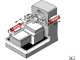 The feed movement of a
lathe has previously been carried out manually. In future, this
is to be performed automatically by a hydraulic control system.
The feed movement must be adjustable and remain constant even
with changing tool loads. Since a simple throttle valve is not
able to provide a constant feed speed under changing load, a
2-way flow control valve must be used. On the basis of a circuit
diagram with data for the no- load situation, values for
pressures, pressure differences and feed speed under load must be
added. The circuit diagram must be modified to ensure that the
flow control valve is not operative on the return stroke.
Finally, the relationship must be investigated between Q of the
PRV and the feed speed and between D p_2 and the volumetric flow
to the load device.
The feed movement of a
lathe has previously been carried out manually. In future, this
is to be performed automatically by a hydraulic control system.
The feed movement must be adjustable and remain constant even
with changing tool loads. Since a simple throttle valve is not
able to provide a constant feed speed under changing load, a
2-way flow control valve must be used. On the basis of a circuit
diagram with data for the no- load situation, values for
pressures, pressure differences and feed speed under load must be
added. The circuit diagram must be modified to ensure that the
flow control valve is not operative on the return stroke.
Finally, the relationship must be investigated between Q of the
PRV and the feed speed and between D p_2 and the volumetric flow
to the load device.
In order to prevent the flow control valve from acting as a resistance on the return stroke, a non-return valve is installed parallel to this as a by-pass. The pressure at the PRV remains constant despite the effect of the load. The outlet flow from this is therefore a constant 7 l/min. A constant volumetric flow Q at the PRV in turn means a constant volumetric flow to the load device and thus constant feed speed. Regarding the last question: No matter whether operation is with or without a load, the pressure drop D p_2 at the adjustable throttle remains constant. A constant pressure drop means a constant volumetric flow.
Regarding the necessity for the non-return valve in the by-pass: When flow passes through 2-way flow control valves in the reverse direction, they act either as flow control valves if the regulating restrictor is fully open or non-return valves if the regulating restrictor is closed.