

[64] Circuit diagram: Brake valve
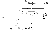 This illustration shows the
correct circuit for the problem in topic
63. This circuit incorporates
not only a brake valve on the piston-rod side but also a
non-return valve on the inlet side via which oil can be taken in
from a reservoir during the vacuum phase following the closure of
the directional control valve.
This illustration shows the
correct circuit for the problem in topic
63. This circuit incorporates
not only a brake valve on the piston-rod side but also a
non-return valve on the inlet side via which oil can be taken in
from a reservoir during the vacuum phase following the closure of
the directional control valve.
The following animation shows the events which occur in the two working lines.