2.19 Database Diagrams
|
|
Prerequisite: In order to use database diagrams you need Microsoft Visio 2010 or later.
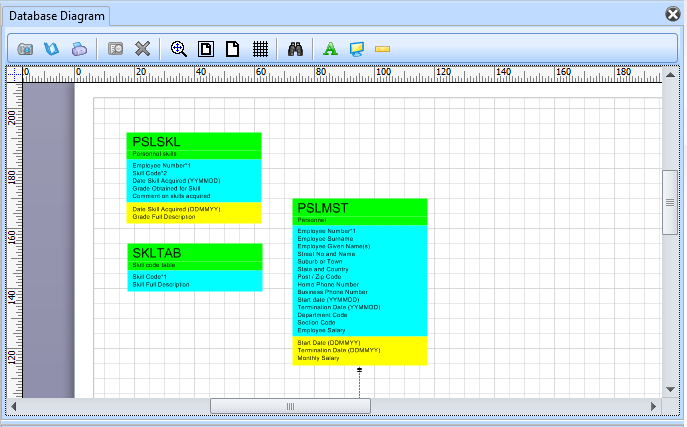
Database Diagrams provide an up-to-date graphical view of the file definitions that are stored in your LANSA Repository.
The diagrams are stored in the LANSA directory on your PC. Therefore, database diagrams that you create are not visible to others who may be using the same Repository as you are using.
You can place any physical file anywhere on the diagram by dragging and dropping from the editor's Repository tab. The diagrams show relationships between files defined by access routes.
You have the option of adding related files when manually adding files to a diagram.
To open the definition of a file shown on the diagram, right-click and choose Open file for edit from the context menu.
You can save diagrams for later viewing or as a separate, standalone Visio document for use in documents and presentations.
Files in Database Diagrams
The Database Diagram shows physical files that reside in the LANSA Repository. This is how the Personnel Skills file PSLSKL from LANSA Demonstration Personnel Application is shown on the diagram:
Each file has three portions:
- At the top, a green section which shows the name and description of the file
- In the middle, a blue section shows the descriptions of all real fields belonging to the file. The asterisks after the first two field descriptions indicate that the fields are primary keys of the file. In addition, the number after the asterisk shows the key positions of the fields in the file.
- At the bottom, a yellow section shows the descriptions of all virtual fields belonging to the file.
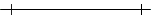
In addition, the diagram shows the relationships between physical files as defined by access routes defined for the files. These are depicted by lines which join the file shapes. The lines have different shapes at their ends according to the properties of the access routes, which specify the type of relationship. For example:
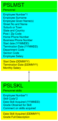
The example shows the relationship between the Personnel and Personnel Skills files. Note that the Personnel end of the line has a single line through it and the Personnel Skills end of the line has three prongs. This denotes that there is a one-to-many relationship between the Personnel and Personnel Skills files, as defined by their access routes.
The different types of line end shapes are discussed later in this guide.
Access Routes in Database Diagrams
Access route definitions are the means by which the diagram viewer determines that files are related. These relationships are shown as lines between file shapes on the diagram.
The end of the connecting line shows the type of relationship depicted:
|
|
A mandatory one-to-one join, where the source Access Route has a maximum records property of 1 and a default action of ABORT. |
|
|
An optional one-to-one join, where the source Access Route has a maximum records property of 1 and a default action of IGNORE. |
|
|
A one-to many, parent/child relationship, where the source Access Route has a maximum records property of 9999. |
|
|
A relationship with Access Route properties that differ from those above. |


Note that when Access Route definitions in both the source and target files of the relationship match, the connecting line is colored black on the diagram. This denotes a fully defined relationship between the two files.
When there is not a matching Access Route, the connecting line is colored pink on the diagram. This denotes a partially defined relationship between the two files.