Dynamic Generation Timing Diagrams
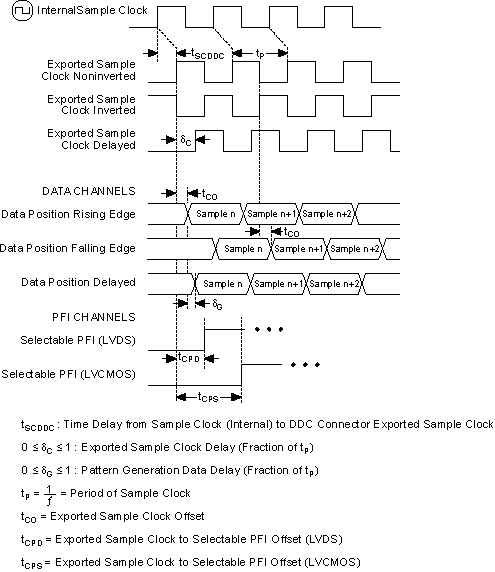
The following figure illustrates the data and clock positions available when generating waveforms with the NI 656x in SDR mode. For simplicity, the data is shown delayed by 25% of the clock period; however, this value can vary between 0% and 100%, with some exceptions. Refer to the NI 656x specifications for more information about valid ranges.
 |
Note Data generation on the rising or falling clock edge is per channel selectable. However, if you use the delayed position, all the data and PFI channels must be delayed, and the delay value must be constant across all channels. |

For more information about using NI-HSDIO to adjust the data position, refer to Configuring Data Position.
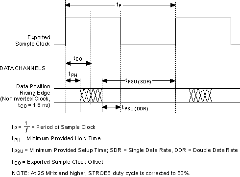
Generation Provided Setup and Hold Times Timing Diagram
