Termination
Unlike systems designed for lower speed applications, in high-speed digital systems, simple passive circuit elements like wires, cables, and chip PCB interconnections can significantly affect signal quality. High-speed digital edges contain frequency components that are several times the effective toggle rate of that signal. For example, a digital edge with a rise time of 1.5 ns contains significant energy in frequencies up to 333 MHz, regardless of toggle rate. When designing systems using NI digital waveform generator/analyzers, you must have a basic understanding of both transmission lines and termination so that you can maximize signal quality and minimize the effects of signal reflections.
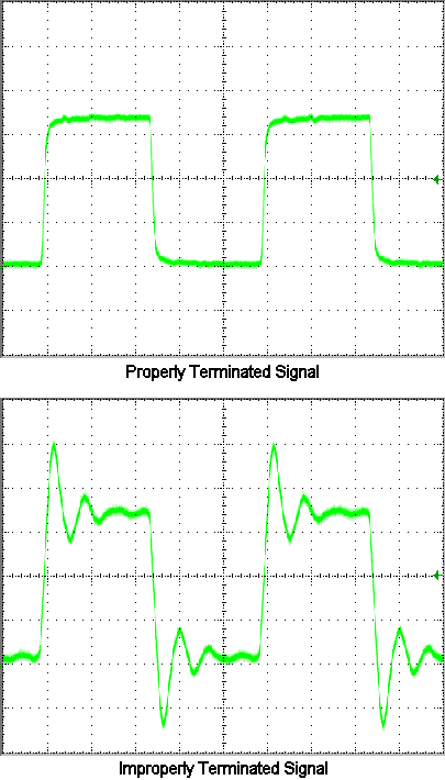
The signals in the following figures show identical digital waveforms generated by an NI PXI-6552. The first figure shows a properly terminated waveform where the test system was designed with a careful understanding of both transmission lines and termination. The second figure shows a waveform from an unterminated system where transmission line effects and termination were not considered.

Consider the following key areas when designing your test system:
- Zs—The impedance at the source of the transmission line
- Z0—The characteristic AC impedance of the transmission line
- Zt—The impedance at the destination of the transmission line
By carefully controlling these three elements of your system, you can achieve the best possible results. Leaving these three elements uncontrolled can result in the type of signal distortion shown in the improperly terminated signal and produce the following results:
- Signals that exceed specified high-level and low-level thresholds (overshoot and undershoot)
- Signals that have false edges (ringing)
- Signals that have reduced operating margins (degraded eye diagram caused by inter-symbol interference)
- Potential physical damage or overheating of driver/receiver components in extreme cases
Refer to Terminating Your Module for information about series and parallel resistor termination that is commonly applicable to your NI digital waveform generator/analyzer.