Dynamic Acquisition Timing Diagrams
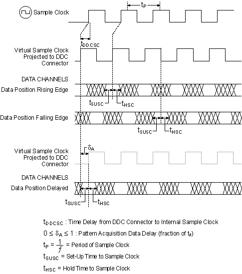
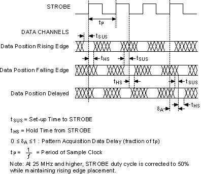
The following diagram illustrates the data positions available when acquiring waveforms with the NI 656x in SDR mode. For simplicity, the delayed data is shown delayed by 0.25 clock periods; however, this value can vary between zero and one, with some exceptions.
Using the Sample Clock as the Acquisition Clock

Using STROBE as the Acquisition Clock
