Differential Voltage Levels
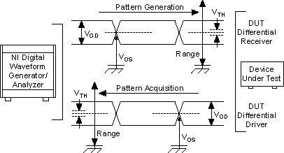
Unlike single-ended signals, differential signals are transmitted in parity. That is, instead of a single conductor referenced to ground, two conductors, referenced to each other, transmit data. The digital driver still drives two voltages, as in the single-ended case. The receiver, however, interprets the signals based on the voltage difference between the pair of signals — not on a reference to ground. For the differential digital signal to be interpreted as a binary 0, the signal must be less than its complementary signal by more than a particular value, shown as VTH in the figure below. VTH varies and is specified by the particular logic family.
Since the conductors are referenced and transmitted together, by using differential signals you can achieve higher noise immunity in your signals. A benefit to this is that you can allow much smaller signal swings, so you can transmit data farther, faster, and at a fraction of the power
Since differential signals reference a positive signal to a complementary signal, across a specified differential impedance, voltage levels are typically specified from a differential, rather than an absolute, perspective (depending on the standard). For example, the absolute voltage levels of an LVDS transmission pair across a 100 Ω differential terminating impedance may have a VOH of 1.4 V on the positive conductor and a VOL of 1.1 V on the complementary conductor. The differential voltage would then be called out as the difference between the two—300 mV, shown as VOD in the following figure. There is, however, a common-mode component of the signal, shown as VOS in the following figure, that is also called out by most differential specifications and is referenced to common.
For differential NI digital waveform generator/analyzers, the voltage levels are defined as follows:
- Differential Output Voltage (VOD)—The difference in voltage between the positive and complementary conductors of a differential transmission. You can think of this value as the difference of the two conductors.
- Offset Voltage (VOS)—The common mode of the differential signal. You can think of this value as the average of the two conductors.
- Threshold Voltage (VTH)—The differential voltage threshold at which the receiver registers a valid logic state.
- Input Voltage Range (VRANGE)—The absolute voltage, referenced to common, allowed by the receiver.
When connecting a differential NI digital waveform generator/analyzer to a DUT, ensure that the interface voltage levels are compatible. The relationship between the differential NI device voltage levels and the DUT voltage levels are shown in the following figure.
The total NIM is computed by the following formula:
NIM = [min (|Generation VOD - DUT VTH|,|DUT VOD - Acquisition VTH|)]
The NI SHB12X-B12X shielded cable for differential high-speed digital signals provides excellent protection against external noise sources.