Dynamic Acquisition Timing Diagrams
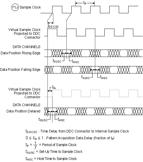
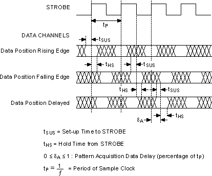
The following diagram illustrates the data positions available when acquiring waveforms with the NI 655x. For simplicity, the delayed data is shown delayed by 25% of the clock period; however, this value can vary between 0% and 100%.
Using the Sample Clock as the Acquisition Clock

Using STROBE as the Acquisition Clock
