Input Protection
DIO<0..19>, PFI <0..3>, DDC CLK OUT, and STROBE are protected using diode clamps connected to the positive and negative voltage supplies. The following figure illustrates this circuit.

The entire I/O circuit is shown in the Channel Electronics diagram.
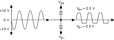
These diodes act as open circuits unless the I/O voltage levels go above Vp+ or below Vp-. When the I/O voltage exceeds Vp+/Vp-, the diodes become short circuits, clamping the input voltage to Vp+/Vp-. Therefore, these diodes prevent input voltages from going more than a diode drop, or approximately 0.5 V, beyond the positive or negative protection rails. The following diagram demonstrates the effect of the clamp.

The NI 655x is protected from instantaneous shorts to legal DUT voltages. Refer to the NI 655x specifications for details on device input protection.