Single-Ended Voltage Levels
For single-ended devices, voltage levels are usually specified in terms of the voltage placed on the output terminal when driving a high level signal or when driving a low level signal, and by the voltage required on the input terminal for the signal to be recognized as a high or low level signal.
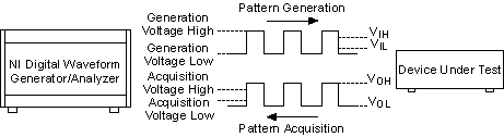
For the NI digital waveform generator/analyzers, the single-ended voltage levels are defined as follows:
- Generation Voltage High Level—When configured for active drive generation, this is the voltage produced at the channel electronics when the Pattern Generation Engine generates a binary one. When configured for open collector generation, Generation Voltage High Level is equivalent to setting the data channel to a high-impedance state.
- Generation Voltage Low Level—The voltage produced at the channel electronics when the Pattern Generation Engine generates a binary zero.
- Acquisition Voltage High Level—The voltage level at or above which the Pattern Acquisition Engine senses a binary one.
- Acquisition Voltage Low Level—The voltage level at or below which the Pattern Acquisition Engine senses a binary zero.
 |
Note On the NI 655x devices these levels are configurable. |
When connecting an NI digital waveform generator/analyzer to a device under test (DUT), you must ensure that the interface voltage levels are compatible. The relationship between the single-ended voltage levels and the DUT voltage levels are shown in the following figure.
To accurately communicate with a DUT, configure the NI module such that the following conditions are met:
- Generation Voltage High Level ³ DUT VIH
- Generation Voltage Low Level £ DUT VIL
- Acquisition Voltage High Level £ DUT VOH
- Acquisition Voltage Low Level ³ DUT VOL
- Acquisition Voltage High Level > Acquisition Voltage Low Level
The extra margin between the voltage level being driven by the source and the voltage level required at the destination is known as the noise immunity margin (NIM). The NIM indicates the amount of noise tolerable on the connecting cable with a data bit being received in correctly. The total NIM is computed by the following formula:
NIM = [min (|Generation Voltage High - DUT VIH|, |Generation Voltage Low - DUT VIL|,
|DUT VOH - Acquisition Voltage High|, |DUT VOL - Acquisition Voltage Low|)]
The NI SHC68-C68-D2 shielded cable for single-ended high-speed digital signals provides excellent protection against external noise sources. However, if your system operates in a particularly noisy environment and is having difficulty with incorrect data bits, consider increasing the NIM, if possible.