Eliminating Round Trip Delay
While performing a stimulus-response application, the time required for data to move from the digital tester, through the cable and DUT, and back to the tester is known as round trip delay (RTD).
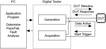
One way to account for round-trip delay is by exporting a signal with an edge that is synchronous to the start of the stimulus data. This signal should be routed through equal lengths of cable to the acquisition Start trigger so that the signal has the same round trip delay as the data. The Data Active event can be used to accomplish this task, since it is synchronous to the start of the stimulus data.
The following figure illustrates the signal routing involved in elimination round trip delay.

For example, you can export the Data Active event on PFI 1 and route it to PFI 2, which you can configure as the acquisition Start trigger source. Then you can export the generation Sample clock to DDC CLK OUT and configure the acquisition Sample clock source as STROBE. Match your cable lengths so that the signals are routed with the same round trip delay as the data. This method ensures that clocks, control signals, and data signals all arrive at the device at the same time.
Another method to account for round-trip delay is to internally route a delayed version of your Data Active event to your acquisition Start trigger. To use this method, you must first know your total round-trip delay. Once known, set the Data Active Internal Route Delay property or the NIHSDIO_ATTR_DATA_ACTIVE_INTERNAL_ROUTE_DELAY attribute to that number of clock cycles. Then set the Data Position Delay property or the NIHSDIO_ATTR_DATA_POSITION_DELAY attribute to the desired fractional delay.