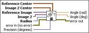
IMAQ Rotation Detect VI
Owning Palette: CaliperInstalled With: NI Vision Development ModuleDetects the rotational shift between two images, generally between a reference image, with the part being inspected at a known orientation, and another image that has the part in an unknown position. This VI extracts pixel values around a circular region in the reference image. These values then are compared to the same region in Image 2. The algorithm looks for the rotational shift between those two samples. To speed up the process, adjust the requested precision of the result.


 |
Reference Center contains coordinates of the center of a circular region in the reference image. Pixel values along this region in the reference image are used as features for computing the rotational shift. |
||||||
 |
Image 2 Center contains coordinates of the center of a circular region in Image 2. The pixel values along this region in Image 2 are used to compute the rotational shift. |
||||||
 |
Reference Image is the reference to the image containing the part to be inspected at a known position. |
||||||
 |
Image 2 is the reference to the image that contains the part to be inspected at an unknown rotational shift. |
||||||
 |
Radius is the radius of the circular regions in both images. Pixel values along this region in the two images are used to detect the rotation angle between the two images. |
||||||
 |
error in (no error) describes the error status before this VI or function runs. The default is no error. If an error occurred before this VI or function runs, the VI or function passes the error in value to error out. This VI or function runs normally only if no error occurred before this VI or function runs. If an error occurs while this VI or function runs, it runs normally and sets its own error status in error out. Use the Simple Error Handler or General Error Handler VIs to display the description of the error code. Use error in and error out to check errors and to specify execution order by wiring error out from one node to error in of the next node.
|
||||||
 |
Precision (degrees) is the sampling period of the pixel values extracted from the circular region. The speed of this VI is affected directly by the sampling period. If the sampling period is high (the number of samples along the circular region are few), the processing speed of the VI increases at the cost of reduced accuracy in the computed rotational shift. In many cases, a precision higher than five degrees is not needed to position the regions of inspection of a part. The default is 5. |
||||||
 |
Angle (rad) returns the angle in radians corresponding to the shift giving the best match between the two samples. |
||||||
 |
Angle (deg) returns the angle in degrees corresponding to the shift giving the best match between the two samples. |
||||||
 |
error out contains error information. If error in indicates that an error occurred before this VI or function ran, error out contains the same error information. Otherwise, it describes the error status that this VI or function produces. Right-click the error out indicator on the front panel and select Explain Error from the shortcut menu for more information about the error.
|
Examples
Refer to the following for an example that uses this VI.
- LabVIEW\examples\Vision\3. Applications\Rotating Part Example.llb


