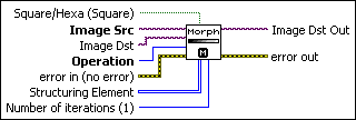
IMAQ GrayMorphology VI
Owning Palette: MorphologyInstalled With: NI Vision Development ModulePerforms grayscale morphological transformations. All source and destination image types must be the same. The connected source image for a morphological transformation must have been created with a border capable of supporting the size of the structuring element. A 3 × 3 structuring element requires a minimal border of 1, a 5 × 5 structuring element requires a minimal border of 2, and so on. The border size of the destination image is not important.
 |
Note This VI modifies the source image. If you need the original source image, create a copy of the image using the IMAQ Copy VI before using this VI. |


 |
Square/Hexa (Square) specifies whether to treat the pixel frame as square or hexagonal during the transformation. The default is square. |
||||||||||||||
 |
Image Src is a reference to the source image. |
||||||||||||||
 |
Image Dst is a reference to the destination image. |
||||||||||||||
 |
Operation specifies the type of morphological transformation procedure to use. The default is AutoM. You can choose from the following values:
|
||||||||||||||
 |
error in (no error) describes the error status before this VI or function runs. The default is no error. If an error occurred before this VI or function runs, the VI or function passes the error in value to error out. This VI or function runs normally only if no error occurred before this VI or function runs. If an error occurs while this VI or function runs, it runs normally and sets its own error status in error out. Use the Simple Error Handler or General Error Handler VIs to display the description of the error code. Use error in and error out to check errors and to specify execution order by wiring error out from one node to error in of the next node.
|
||||||||||||||
 |
Structuring Element is a 2D array that contains the structuring element to apply to the image. The size of the structuring element (the size of this array) determines the processing size. A structuring element of 3 × 3 is used if this input is not connected. |
||||||||||||||
 |
Number of iterations (1) is the number of times the VI performs a dilate or erode operation. |
||||||||||||||
 |
Image Dst Out is a reference to the destination image. If Image Dst is connected, Image Dst Out is the same as Image Dst. Otherwise, Image Dst Out refers to the image referenced by Image Src. |
||||||||||||||
 |
error out contains error information. If error in indicates that an error occurred before this VI or function ran, error out contains the same error information. Otherwise, it describes the error status that this VI or function produces. Right-click the error out indicator on the front panel and select Explain Error from the shortcut menu for more information about the error.
|
Details
A structuring element must have odd-sized dimensions so that it contains a central pixel. If one of the dimensions for the structuring element is even, the function does not take into account the odd boundary, farthest out on the matrix. For example, if the input structuring element is 6 × 4 (X = 6 and Y = 4), the actual processing is performed at 5 × 3. Both the sixth line and the fourth row are ignored. The processing speed is correlated with the size of the structuring element. For example, a 3 × 3 structuring element processes nine pixels, and a 5 × 5 structuring element processes 25 pixels.


