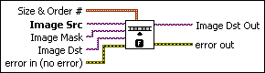
IMAQ NthOrder VI
Owning Palette: FiltersInstalled With: NI Vision Development ModuleOrders, or classifies, the pixel values surrounding the pixel being processed. The data is placed into an array and the pixel being processed is set to the nth pixel value, the nth pixel being the ordered number.
 |
Note This VI modifies the source image. If you need the original source image, create a copy of the image using the IMAQ Copy VI before using this VI. |
|
Note Refer to the NI Vision Concepts Manual for more information about this filter. |


 |
Size & Order # is a cluster that specifies the X Size, Y Size, and Order # variables. The default values correspond to a 3 × 3 median filter.
|
||||||
 |
Image Src is a reference to the source image. |
||||||
|
Image Mask is an 8-bit image that specifies the region of the small image that will be copied. Only those pixels in the Image Src (Small) image that correspond to an equivalent non-zero pixel in the mask image are copied. All other pixels keep their original values. The entire image is processed if Image Mask is not connected. |
||||||
|
Image Dst is a reference to the destination image. |
||||||
 |
error in (no error) describes the error status before this VI or function runs. The default is no error. If an error occurred before this VI or function runs, the VI or function passes the error in value to error out. This VI or function runs normally only if no error occurred before this VI or function runs. If an error occurs while this VI or function runs, it runs normally and sets its own error status in error out. Use the Simple Error Handler or General Error Handler VIs to display the description of the error code. Use error in and error out to check errors and to specify execution order by wiring error out from one node to error in of the next node.
|
||||||
 |
Image Dst Out is a reference to the destination image. If Image Dst is connected, Image Dst Out is the same as Image Dst. Otherwise, Image Dst Out refers to the image referenced by Image Src. |
||||||
 |
error out contains error information. If error in indicates that an error occurred before this VI or function ran, error out contains the same error information. Otherwise, it describes the error status that this VI or function produces. Right-click the error out indicator on the front panel and select Explain Error from the shortcut menu for more information about the error.
|


Details
The connected source image must have been created with a border capable of supporting the size of the convolution matrix. A 3 × 3 matrix must have a minimum border of 1, a 5 × 5 matrix must have a minimum border of 2, and so on. The border size of the destination image is not important.
The default for this VI is a 3 × 3 median operation with X = 3, Y = 3, and Order = 4. To change to a 5 × 5 median operation, the cluster must take the values X = 5, Y = 5, and Order = 12. In this last example, the order number is determined by calculating the central pixel number in the array. For a 5 × 5 convolution, Order = 12 (the 13th pixel) because that pixel is the center pixel number for a 2D array of 25 pixels.
A lighter image results when using a higher-order number (such as 7 in a 3 × 3 matrix). Darker images result when using a lower-order number (such as 1 in a 3 × 3 matrix).
A median (center-pixel) operation is advantageous because it standardizes the gray-level values without significantly modifying the form of the objects or the overall brightness in the image. You can use this VI to apply a median filter by selecting the correct order, (f^2-1)/2, where f is the size of the convolution matrix.
If the order value that is entered is 0, the image obtained is representative of the local minimum from the source image. This operation is equivalent to a gray morphology erosion.
If the order value that is passed is equal to the following equation, the obtained image is representative of the local maximum from the source image. This operation is equivalent to a gray morphology dilation.