Standards Tab
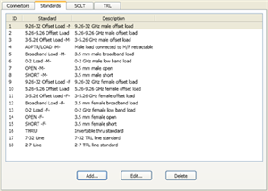
Allows you to Add, Edit or Delete cal standards in a cal kit.
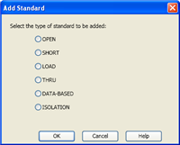
Add Standard (Open, Short, Load, Thru, or Data-based)
Allows you to add standards to the calibration kit file. Choose from: |
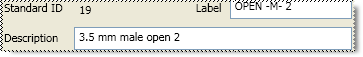
The following fields apply to ALL standard types:
The other areas of the dialog change depending on the type of standard selected. IdentificationStandard ID Number in list of standards Label Type of standard. This usually appears in prompts for standards. Description Description of standard.
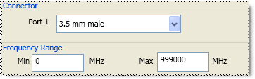
The following fields apply to ALL standard types EXCEPT the Isolation type:
ConnectorIndicates the type and gender (Male, Female, None) of the standard. Thru and Isolation standards have two connectors. Data-Based standards MAY have two connectors. Frequency RangeMin Defines the lowest frequency at which the standard is used for calibration. Max Defines the highest frequency at which the standard is used for calibration.
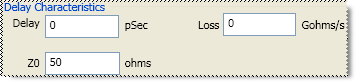
The Delay Characteristics fields apply to MOST standard types:
Delay CharacteristicsDelay Defines the one-way travel time from the calibration plane to the standard in seconds. Z0 Defines the impedance of the standard. Loss Defines energy loss in Gohms, due to skin effect, along a one-way length of coaxial cable.
Other fields are unique to standard type Choose from: |
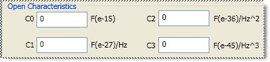
Open Standard
C0, C1, C2, C3 Specifies the fringing capacitance.
These are the unique fields of the dialog. See the areas that are common to all standards.
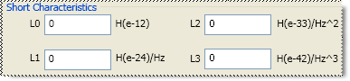
Short Standard
L0, L1, L2, L3 Specifies the residual inductance.
Load Standard
Choose from the following
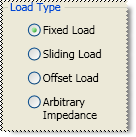
Fixed Load Specifies the load type as Fixed. The fixed load is assumed to be a perfect termination without reflection.
A sliding load is defined by making multiple measurements of the device with the sliding load element positioned at various marked positions of a long transmission line. The transmission line is assumed to have zero reflections and the load element has a finite reflection that can be mathematically removed using a least squares circle fitting method.
A sliding load cal can be very accurate when performed perfectly. It can also be very inaccurate when not using proper technique. For accurate results, closely follow the users manual instructions for the sliding load.
Arbitrary Impedance
Specifies the load type that has an impedance value different from system Z0. An arbitrary impedance device is similar to a fixed load except that the load impedance is NOT perfect. Early firmware releases of the PNA series used a fixed resistance value. A complex terminating impedance has been added to allow for more accurate modeling of circuit board or on-wafer devices.
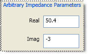
The following Complex Impedance settings are available ONLY when Arbitrary Impedance is selected.
Real The real portion of the impedance value.
Imaginary The imaginary portion of the impedance value.
In Jan 2006, Offset Load definitions were added to TRL and Waveguide Cal Kit files. Using an Offset Load standard results in a more accurate calibration than with a Broadband Load. Therefore, when performing a calibration using one of the modified Cal Kit definitions, you may be prompted to connect more standards than before this change. To revert to using the Broadband Load Standard without offset, do the following:
Click Calibration, then Advanced Modify Cal Kit
Select the kit, then click Edit Kit
Under Class Assignments, click Edit
Select Calibration Kit Class S11C (Loads)
Under Selected Standards, select Broadband Load, then click Move Up until the standard is at the top of the list. This will ensure that the Broadband Load is used first.
About Offset Load
An offset load is a compound standard consisting of a load element and two known offset elements (transmission lines) of different length. The shorter offset element can be a zero-length (Flush-thru) offset. The load element is defined as a 1-port reflection standard. An offset load standard is used when the response of the offset elements are more precisely known than the response of the load element. This is the case with waveguide. Measurement of an offset load standard consists of two measurements, one with each of the two offset elements terminated by the load element. The frequency range of the offset load standard should be set so that there will be at least a 20 degree separation between the expected response of each measurement.
To specify more than two offset elements, define multiple offset load standards. In cases where more than two offsets are used, the frequency range may be extended as the internal algorithm at each frequency will search through all of the possible combinations of offsets to find the pair with the widest expected separation to use in determining the actual response of the load element.
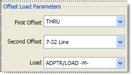
The following Offset Load settings are available ONLY when Offset Load is selected.
First Offset Standard
Second Offset Standard
Load Standard
Thru Standard
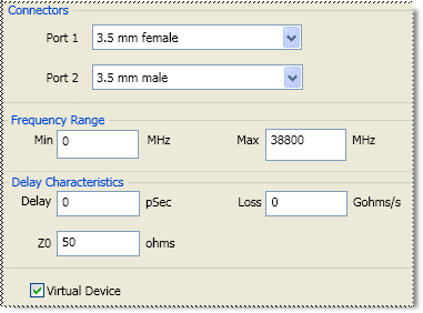
Connectors - Defines connector type at both ends of the Thru standard.
Virtual Device
Most cal kits have only one Thru standard definition for SOLT calibrations. For these cases, use the default selections (checked for zero-length Thrus and cleared for non-zero-length Thrus).
This checkbox is used to make forward and reverse measurements of your Thru standard for the same pair of ports in two separate steps. This is NOT common for zero-length (Flush) Thru standards.
When checked, calibration prompts involving that Thru will omit the Description. For example “Connect port 1 to port 2”. This is the common prompt for Flush-Thru standards.
When cleared, calibration prompts for that Thru will include the Description. For example “Connect <standard description> between ports 1 and 2”.
To make forward and reverse measurements of your Thru standard for the same pair of ports as two separate steps, do the following:
Create separate definitions of the Thru standard(s) using the same settings, except for the Label and Description. Clear this checkbox for BOTH definitions.
For one Thru definition, in the label and description include the word 'FORWARD' to prompt the operator to use this standard for the forward measurement. Assign this standard to the SOLT “FWD TRANS” and “FWD MATCH” classes of the cal kit.
For the Thru definition, in the label and description include the word 'REVERSE' to prompt the operator to use this standard for the reverse measurement. Assign this standard to the SOLT “REV TRANS” and “REV MATCH” classes of the cal kit.
When you perform SOLT calibrations using this cal kit, the forward measurements of the Thru will be measured in one connection step, and the reverse measurements in another.
Data-Based Standard
Note: To learn how to modify data-based standard files, visit http://na.support.keysight.com/pna/dbcal.html
Learn about the relative accuracy of Databased versus Polynomial Cal Kits.
The modified file can then be uploaded into the VNA.
Click Load Data File, then navigate to the *.dat file which is provided with the data-based Cal Kit. Both Response data and Accuracy (Uncertainty) data is provided in a single *dat file.
For Advanced Users
Response data can be loaded from a *.s2p or *.cti file.
Accuracy data can be loaded from a *.cti file. Starting with Option 015, you can also load data from a *.dsd (S-parameter Data Standard Definition) file. The *.dsd file contains both Response data and Accuracy (Uncertainty) data where the accuracy data is in covariant form. Learn more about Dynamic Uncertainty.
Virtual Device
This checkbox is displayed for a Data-Based cal standard when the standard has been defined to have 2 ports.
When Cleared (default) calibration prompts for that standard will include it’s Description. For example “Connect <standard description> between ports 1 and 2”.
When Checked, calibration prompts for that standard will NOT include its Description, so the prompt will be worded as if the data-based standard is a zero-length Thru connection. For example “Connect port 1 to port 2”.
Isolation Standard
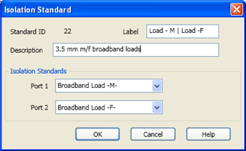
The pair of loads are considered one standard.
Both loads are connected to the VNA and measured with the same prompt.
Available at the bottom of every tab
Save As - Allows you to save the cal kit to a new file name and type.
Save - Saves the cal kit to the same file name and type.
Close - Closes the cal kit editing session. The file is NOT saved automatically.
Last modified:
2-Apr-2013 |
New file |