Reflection Accuracy on Low-Loss 2-Port Devices
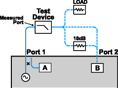
To make accurate reflection measurements that have a 1-port calibration, you should terminate the unmeasured port.
Other topics about Optimizing Measurements
Why Terminate the Unmeasured Port
A 2-port calibration corrects for all 12 twelve error terms. A 1-port calibration corrects for directivity, source match and frequency response, but not load match. Therefore, for highest accuracy, you must make the load match error as small as possible. This especially applies for low-loss, bi-directional devices such as filter passbands and cables. You do not need to be concerned with load match when you are measuring a device with high reverse isolation, such as an amplifier.
How to Terminate the Unmeasured Port
Use one of the following methods:
-
Connect a high-quality termination load (from a calibration kit, for example) to the unmeasured port of your device. This technique yields measurement accuracy close to that of a Full SOLT 2-port calibration.
-
Connect the unmeasured port of your device directly to the analyzer, inserting a 10 dB precision attenuator between the device output and the analyzer. This improves the effective load match of the analyzer by approximately twice the value of the attenuator, or 20 dB.

Resulting Measurement Uncertainty
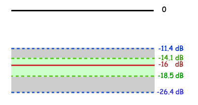
The following graph illustrates the measurement uncertainty that results from terminating with and without a precision 10 dB attenuator on the output of the test device.

Legend
|
|
Filter Reflection |
|
------------- |
Uncertainty with attenuator |
|
................ |
Uncertainty without attenuator |
The calculations below show how adding a high-quality 10 dB attenuator improves the load match of the analyzer.
Note: The corresponding linear value is shown in parentheses.
|
Network Analyzer: |
|
|
Load match (NALM) |
= 18 dB (.126) |
|
Directivity (NAD) |
= 40 db (.010) |
|
Filter: |
|
|
Insertion loss (FIL) |
= 1dB (.891) |
|
Return loss (FRL) |
= 16 dB (.158) |
|
Attenuator: |
|
|
Insertion loss (AIL) |
= 10 dB (.316) |
|
SWR (ASWR) |
= 1.05 (.024) |
Calculations:
|
|
Without Attenuator |
With Attenuator |
|
rNA
|
= (FIL)*(NALM)*(FIL) |
= (FIL)*(AIL)*(NALM)*(AIL)*(FIL) |
|
rAttenuator |
NA |
= (FIL)*(ASWR)*(FIL) |
|
Worst Case Error (EWC) |
= rNA |
= rNA + rAttn. |
|
|
||
|
Uncertainty Adds |
= -20log(FRL)+(EWC)+(NAD) |
= -20log(FRL)+(EWC)+(NAD) |
|
|
||
|
Uncertainty Subtracts |
= -20log(FRL)-(EWC)-(NAD) |
= -20log(FRL)-(EWC)-(NAD) |