Phase Measurement Accuracy
You can increase the accuracy of phase measurements by using the following features.
See Also
Learn more about Phase measurements
Electrical delay is a mathematical function that simulates a variable length of lossless transmission line.
Use the electrical delay feature to compensate for the linear phase shift through a device. This feature allows you to look at only the deviation from linear phase of the device.
You can set the electrical delay independently for each measurement trace.
How to set Electrical Delay |
|
|
Using front-panel hardkey [softkey] buttons |
Using Menus |
|
|
|
|
|
|
Electrical Delay Specifies the value of delay added or removed, in Time or Distance. This compensates for the linear phase shift through a device. You can set the electrical delay independently for each measurement trace. Click the Step Velocity Factor Specifies the velocity factor that applies to the medium of the device that was inserted after the measurement calibration. The value for a polyethylene dielectric cable is 0.66 and 0.7 for PTFE dielectric. 1.0 corresponds to the speed of light in a vacuum. Velocity factor can also be set from the Port Extensions dialog and Time Domain Distance Marker Settings. Softkey Display Allows you to enter delay in either Time or Distance using the softkeys and Active Entry toolbar. Distance Units Select from Meters, Inches, or Feet. The step size will not change automatically when this value is changed. Learn more about Step Size. MediaCoax Select if the added length is coax. Also specify the velocity factor of the coax. Waveguide Select if the added length is waveguide. Also specify the low frequency cutoff of the waveguide. Cutoff Freq Low frequency cutoff of the waveguide. Learn about Electrical Delay (scroll up) |
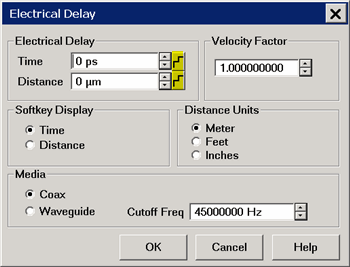
 icon next to either Time or Distance to start the
|
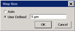
Changes the step size that occurs when the Time or Distance up/down arrows are pressed on the Electrical Delay dialog. Auto Step Size is set to the default value. User Defined Enter a step size value, then click OK. This value remains the same when the units are changed. For example if a step size of 12 is entered on this dialog, then you change the units from Inches to Feet, the step size of 12 inches becomes 12 feet, not 1 feet. Therefore, change the units first, then set the step size. |
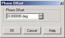
Phase offset mathematically adjusts the phase measurement by a specified amount, up to 360°. Use this feature in the following ways:
-
Improve the display of a phase measurement. This is similar to the way you would change the reference level in an amplitude measurement. Change the phase response to center or align the response on the screen.
-
Emulate a projected phase shift in your measurement. For example, if you know that you need to add a cable and that the length of that cable will add a certain phase shift to your measurement, you can use phase offset to add that amount and simulate the complete device measurement.
How to set Phase Offset |
|
|
Using front-panel |
Using Menus |
|
|
|
|
|
|
Phase Offset Type a value or use the up and down arrows to select any value up to 360 degrees. Learn about Phase Offset (scroll up) |
Spacing Between Frequency Points (Aliasing)
The analyzer samples data at discrete frequency points, then connects the points, creating a trace on the screen.
If the phase shift through a device is >180° between adjacent frequency points, the display can look like the phase slope is reversed. This is because the data is undersampled and aliasing is occurring.
If you are measuring group delay and the slope of the phase is reversed, then the group delay will change sign. For example, the following graphic shows a measurement of a SAW bandpass filter.
-
The left measurement has 51 points and indicates the group delay is negative, which is a physical impossibility. That is, the response is below 0 seconds reference line.
-
The right measurement shows an increase to 201 points which indicates the group delay is positive. That is, the response is above the 0 seconds reference line.
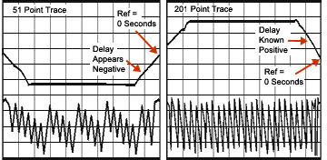
Tip: To check if aliasing might be occurring in a measurement, either increase the number of points or reduce the frequency span.