Absolute Output Power
An absolute output-power measurement displays absolute power versus frequency.
See other Amplifier Parameters topics
What is Absolute Output Power?
An absolute-output power measurement displays the power present at the analyzer's input port. This power is absolute-it is not referenced (ratioed) to the incident or source power. In the log mag format, values associated with the grid's vertical axis are in units of dBm, which is the power measured in reference to 1 mW.
-
0 dBm = 1 mW
-
-10 dBm = 100 mW
-
+10 dBm = 10 mW
In the linear mag format, values associated with the grid's vertical axis are in units of watts (W).
Why Measure Absolute Output Power?
Absolute output power is measured when the amplifier's output must be quantified as absolute power rather than a ratioed relative power measurement. For example, during a gain compression measurement, it is typical to also measure absolute output power. This shows the absolute power out of the amplifier where 1-dB compression occurs.
The output power of the amplifier should be sufficiently attenuated if necessary. Too much output power could:
-
-
Damage the analyzer receiver
-
Exceed the input compression level of the analyzer receiver, resulting in inaccurate measurements.
-
Attenuation of the amplifier's output power can be accomplished using either attenuators or couplers
The amplifier may respond very differently at various temperatures. The tests should be done when the amplifier is at the desired operating temperature.
Do the following to measure absolute output power:
-
Preset the analyzer.
-
Select an unratioed power measurement (receiver B). Learn how.
-
Set the analyzer's source power to 0 dBm.
-
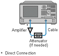
Select an external attenuator (if needed) so the amplifier's output power will be sufficiently attenuated to avoid causing receiver compression or damage to the analyzer's port-2.
-
Connect the amplifier as shown in the following graphic, and provide the dc bias.

-
Select the analyzer settings for your amplifier under test.
-
Remove the amplifier and connect the measurement ports together. Store the data to memory. Be sure to include the attenuator and cables in the test setup if they will be used when measuring the amplifier.
-
Save the instrument state to memory.
-
Reconnect the amplifier.
-
Select the data math function Data/Memory.
-
Scale the displayed measurement for optimum viewing and use a marker to measure the absolute output-power at a desired frequency.
-
Print or save the data to a disk.