Reflection Measurements
Reflection measurements are an important part of network analysis.
What are Reflection Measurements?
To understand reflection measurements, it is helpful to think of traveling waves along a transmission line in terms of a lightwave analogy. We can imagine incident light striking some optical component like a clear lens. Some of the light is reflected off the surface of the lens, but most of the light continues on through the lens. If the lens had mirrored surfaces, then most of the light would be reflected and little or none would be transmitted.
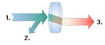
1. Incident 2. Reflected 3. Transmitted
With RF energy, reflections occur when the impedance of two mated devices are not the same. A reflection measurement is the ratio of the reflected signal to the incident signal. Network analyzers measure the incident wave with the R (for reference) channel and the reflected wave with the A channel. Therefore, reflection is often shown as the ratio of A over R (A/R). We can completely quantify the reflection characteristics of our device under test (DUT) with the amplitude and phase information available at both the A and R channel. In S-parameter terminology, S11 is a reflection measurement of port1 of the device (the input port); S22 is a reflection measurement of the port 2 (the output port)
Why Make Reflection Measurements?
One reason we make reflection measurements to assure efficient transfer of RF power. We do this because:
-
RF energy is not cheap. When energy is reflected, that means less energy is transmitted to where it is intended to go.
-
If the reflected energy is large, it can damage components, like amplifiers.
For example, in the following graphic, the radio station on the left is not operating at peak efficiency. The amplifier impedance is not the same as the transmission line, and the transmission line impedance is not the same as the antenna. Both of these conditions cause high reflected power. This condition results in less transmitted power, and the high reflected power could damage the amplifier.
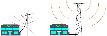
The radio station on the right installed properly "matched" transmission line and antenna. Very little of the transmitted signal is reflected, resulting in increased broadcast power, more listeners, more advertising revenue, and more profit. The amplifier, transmission, and antenna all need to be measured to ensure that reflected power is minimized.
After making a reflection measurement, the reflection data can be expressed in a number of ways, depending on what you are trying to learn. The various expressions are all calculated by the analyzer from the same reflection measurement data. Each method of expressing reflection data can be graphically displayed in one or more formats. For more information, see display formats.
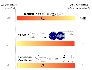
Return Loss
The easiest way to convey reflection data is return loss. Return loss is expressed in dB, and is a scalar (amplitude only) quantity. Return loss can be thought of as the absolute value or dB that the reflected signal is below the incident signal. Return loss varies between infinity for a perfect impedance match and 0 dB for an open or short circuit, or a lossless reactance. For example, using the log magnitude format on the analyzer, the measured reflection value on the screen may be -18dB. The minus sign is ignored when expressing return loss, so the component is said to have 18dB of return loss.
VSWR
Two waves traveling in opposite directions on the same transmission line cause a "standing wave". This condition can be measured in terms of the voltage standing wave ratio (VSWR or SWR for short). VSWR is defined as the maximum reflected voltage over the minimum reflected voltage at a given frequency. VSWR is a scalar (amplitude only) quantity. VSWR varies between one for a perfect match, and infinity for an open or short circuit or lossless reactance.
Reflection Coefficient
Another way of expressing reflection measurements is reflection coefficient gamma (G). Gamma includes both magnitude and phase.
The magnitude portion of gamma is called rho (r). Reflection coefficient is the ratio of the reflected signal voltage to the incident signal voltage. The range of possible values for r is between zero and one. A transmission line terminated in its characteristic impedance will have all energy transferred to the load; zero energy will be reflected and r = 0. When a transmission line terminated in a short or open circuit, all energy is reflected and r = 1. The value of rho is unitless.
Now for the phase information. At high frequencies, where the wavelength of the signal is smaller than the length of conductors, reflections are best thought of as waves moving in the opposite direction of the incident waves. The incident and reflected waves combine to produce a single "standing" wave with voltage that varies with position along the transmission line.
When a transmission line is terminated in its characteristic impedance (Zo) there is no reflected signal. All of the incident signal is transferred to the load, as shown in the following graphic. There is energy flowing in one direction along the transmission line.
|
|
|
Zo |
|
Incident |
Reflected |
|
|
|
(All the incident power is absorbed in the load) |
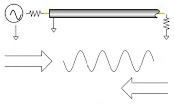
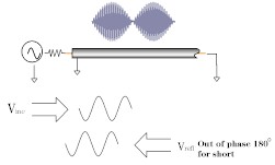
When a transmission line is terminated in a short circuit termination, all of the energy is reflected back to the source. The reflected wave is equal in magnitude to the incident wave (r = 1). The voltage across any short circuit is zero volts. Therefore, the voltage of the reflected wave will be 180 degrees out of phase with the incident wave, canceling the voltage at the load.
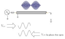
When a transmission line is terminated in an open circuit termination, all of the energy is reflected back to the source. The reflected wave is equal in magnitude to the incident wave (r = 1). However, no current can flow in an open circuit. Therefore, the voltage of the reflected wave will be in phase with the voltage of the incident wave.
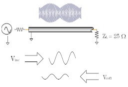
When a transmission line is terminated in a 25 ohm resistor, some but not all of the incident energy will be absorbed, and some will be reflected back towards the source. The reflected wave will have an amplitude 1/3 that of the incident wave and the voltage of the two waves will be out of phase by 180 degrees at the load. The phase relationship will change as a function of distance along the transmission line from the load. The valleys of the standing wave pattern will no longer go to zero, and the peaks will be less than that of the open / short circuit.
For more information, see Phase Measurements.
Impedance
Impedance is another way of expressing reflection data. For more information on Impedance, see Smith Charts.
Summary of the Expressions of Reflection Measurements: