Cal Plane Manager (CPM)
Adapters, fixtures, and probes are often used for DUTs that have non-coaxial interfaces. This could make it difficult to calibrate with traditional cal standards. Cal Plane Manager (CPM) allows you to mathematically remove (de-embed), a characterized adapter, test fixture, or probe head from measurements.
CPM is an enhancement of the existing Characterize Adaptor Macro.
In this topic:
Features
Characterizes adapters and fixtures in SnP files.
Applies the characterizations to existing Cal Sets and channels.
Writes to PNA power loss table using the S2P files of fixtures/adapters.
Reverses the port order of an existing S2P file.
Creates a forward-only S2P file from an existing S2P file.
Cascades two S2P files.
Important Notes
|
Using Cal Plan Manager
|
|
|
Choose from the following, then click Next >:
|
|

Requirements
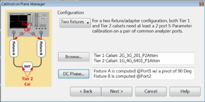
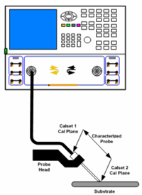
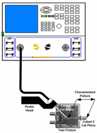
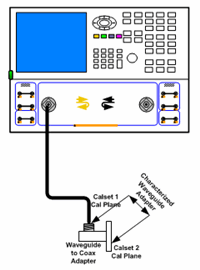
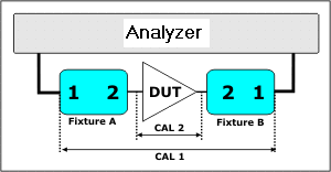
Note: The mechanical switch / attenuator settings of the Tier 1 and Tier 2 cals for CPM MUST be the same settings. Also, when the span or number of points are different between the two cal tiers, there must be sufficient data points to ensure that phase wrapping does NOT occur. This is accomplished when the delta frequency for either calset is less than 12/combined length of the test port cables in meters. ApplicationsThe following images show the calibration planes of the Tier 1 and Tier 2 calibrations:
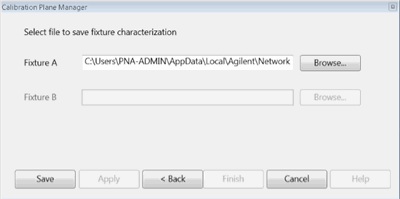
ProcedureConfiguration Select the number of adapter/fixtures to be characterized and de-embedded.
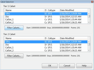
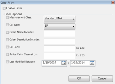
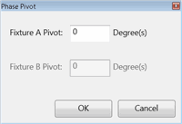
Browse - Starts the following Calset Selection dialog. DC Phase - Starts the Phase Pivot dialog. Click Next > |
In the previous dialog, when a multiport calset is selected for a characterization that involves fewer ports, then select the port in the calset that is used to characterize the fixture/adapter. |

For most devices, the projected phase of S21 at DC crosses the X-axis between 0° and -180°. The phase pivot point specifies the center of the phase window. It is normally 1 Pi wide. The default value of 0° should be adequate for the majority of adapters. However, when characterizing electrically long cables, cables with significant mismatch, or high noise in the measurements, it is possible that the projection of phase goes above 0°. This results in a 180° phase difference between the results computed by CPM versus the results you might get by measuring the same adapter with a 2-port calibration. In these cases, you may have to change the default value to capture the projected phase of S21 at DC. |
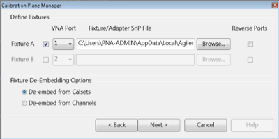
For each Fixture (A and B):
Click Apply to continue to de-embed the fixture. Click Finish to end with the characterization and close the dialog. |
Given one S2P file for each fixture/adapter, this dialog will remove the effects of the fixture/adapter from either:
For each Fixture (A and B)
|
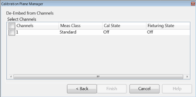
De-embedding is performed and applied to specified channels on the analyzer. Select one more channels currently displayed on the analyzer from which to de-embed the adapter/fixture. |
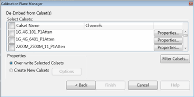
This dialog appears when De-embed from Calsets is selected in the previous dialog. De-embedding is performed and applied to specified Cal Sets. This allows you to easily apply de-embedding in the future by simply applying the de-embedded calset to any channel. Select Calsets: Select the Cal Sets to which de-embedding will be applied. Properties View information about the corresponding calset. Properties
Click Options to start the following dialog.
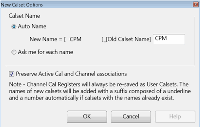
Calset NameAuto Name - By default, a new calset will be created using the old calset name with the specified text ("CPM" by default) appended to the beginning of the name. You can change the specified text. Ask me for each name - Starts the following dialog when OK is pressed. Preserve Active Cal and Channel associations - When checked (default) the new de-embedded Cal Sets will be used to correct the same displayed channels as the current Cal Sets.
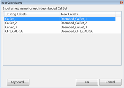
The Existing Calsets that you selected for de-embedding appear in the left column. The proposed New Calset names appear in the right column. To change the new Calset name, select, then edit the name. When finished, click OK. |
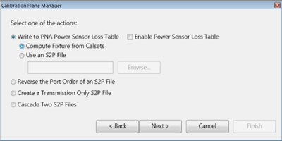
Select one of the actions: Write to PNA power sensor loss table. Loads the S2P Frequency / Loss pairs into the PNA Power Loss Compensation table to compensate for losses that occur when using the device to connect a power sensor to the measurement port during a Source Power Cal.
Note: In the PNA Power Loss Compensation table, loss is expressed as a positive number. CPM assumes that any negative S21 value in the S2P file is a loss and therefore multiplies the S21 values in the file by -1 to express that value as a positive number. This ensures proper handling of the offset during a source power cal.
|
S2P files that are created using CPM ALWAYS reference port 1 of the fixture/adapter on the side closest to the analyzer and port 2 of the fixture/adapter ALWAYS on the DUT side of the device as in the following image.
This action causes ports to be reversed on an existing S2P file.
The resulting file is written in the standard S2P file format.
|

From an existing S2P file, this feature allows you to zero the S11, S22, or both data columns. The original S21 and S12 data are preserved. This is useful for Enhanced Response calibration / de-embedding. Original - Click Browse, then navigate to the file to be modified. Modified - Click Browse, then navigate to the folder and enter or change the filename of the resulting S2P file. The file select dialog allows you to change the format of the data. Click Format, then choose from the following:
ModificationsChoose to Zero the S11, S22, or both data columns. Click Finish. The transmission only file is saved to the specified location. |
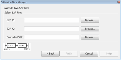
This dialog combines the losses and phase shift of two S2P files into a single S2P file. The stimulus settings of the two input S2P files need not be identical. The frequency range of the cascaded S2P file will be the frequency range that is common between the two input files. In addition, the cascaded S2P file will use the data points of the input file with the denser data points. For example: S2P #1: Frequency range = 1 GHz to 5 GHz; 201 pts. S2P #2: Frequency range = 2 GHz to 6 GHz; 1001 pts. Cascaded S2P: Frequency range = 2 GHz to 5 GHz using the data points of S2P #2. S2P #1 - Click Browse, then navigate to one of the S2P files to be cascaded. S2P #2 - Click Browse, then navigate to the other S2P file to be cascaded. Cascaded S2P - Click Browse, then navigate to a folder and enter the filename of the resulting S2P file. Click Finish. The cascaded file is saved to the specified location. |