External DC Meter Data Conversion
From M9370A / M9371A / M9372A / M9374A / M9375A
External DC Meter Data Conversion
When creating equations using values from an external DC meter, it is important to understand how these values are stored in the PNA's data buffers and the conversion that occurs when used in an equation. For example, when a voltage is read from an external DC meter, the value is displayed on the PNA as you would expect. That is, if you are reading a voltage level of 2 V from the DC meter in a trace, the PNA will display a level of 2 V. However, the value stored in the PNA data buffers is not a voltage but is a unit-less value. Voltage, Amperes, dBm, and Watts values from an external DC meter are converted so that the format matches that of the data in the PNA internal receivers. In this way, all of the formats within the PNA are the same. This information is important when performing analysis using the Equation Editor because the trace data is the converted value.
See Also
Configure a DC Device
The following table shows the formats (which are selected from the Type setting on the External DC Meter Properties dialog) and corresponding equations that convert between external DC meter readings and the PNA representation when using the trace data in an equation.
Note: Z0 is the characteristic impedance (typically 50 Ohms), dcMeter is the value from the external DC meter, and pnaVal is the value stored in the PNA data buffers. All data types are REAL.
Formats |
DC Meter to PNA Data Conversion |
PNA to DC Meter Data Conversion |
| V (volts - default) | +/-*sqrt((dcMeter*dcMeter/Z0)*1000) | +/-*sqrt((pnaVal*pnaVal/1000)*Z0) |
| A (amperes) | +/-*sqrt((dcMeter*dcMeter*Z0)*1000) | +/-*sqrt((pnaVal*pnaVal/Z0)/1000) |
| dBm | pow(10,dcMeter/20) | 20*log(pnaVal) |
| W (watts) | sqrt(dcMeter*1000) | pnaVal*pnaVal/1000 |
| K (kelvin) | N/A | N/A |
| F (degrees) | N/A | N/A |
| C (degrees) | N/A | N/A |
External DC Meter Voltage Example
The following example shows how trace data is converted when used in an equation. In this example, a level of 2 V is read from an external DC meter.
- Configure the external DC meter as described in Configure a DC Device.
- In the External DC Meter dialog, ensure that Type is set to V.
- Select Trace/Chan then New Trace.
- In the New Trace dialog, check Activate, click on the corresponding down arrow in the Numerator column, select the external DC meter from the drop down list, then click OK.
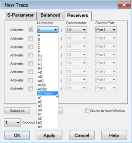
Note: If the external DC meter is not displayed in the list, ensure that Active - Show in UI is checked in the External Device Configuration dialog.
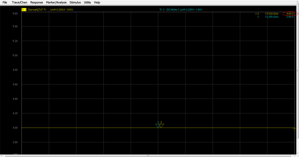
- Trace 1 and Trace 2 should now be displayed on the PNA. Add markers to both traces. The Trace 2 marker should read 2.00 V from the external DC meter.
- Select Trace 1, then select Response, Format, Lin Mag.
- Note that instead of a voltage level of 4.00 V, the Trace 1 marker reads 10.94 U (unit-less value).
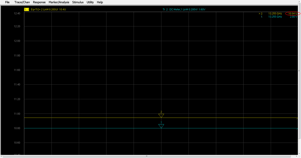
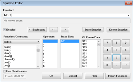
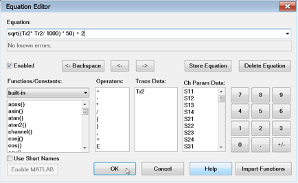
As shown in the table above, a voltage from an external DC meter is converted using sqrt((dcMeter*dcMeter/Z0)*1000). Therefore, substituting 2 for dcMeter in the equation and using 50 as Z0 results in a value of 8.94. Adding a value of 2 to the Trace 2 data, as defined in the Trace 1 equation, results in the displayed marker value of 10.94.
- To ensure that the displayed value is 4 instead of 10.94, which is not useful, use the equation from the PNA to DC Meter Data Conversion column of the table above as follows:
- The Trace 1 marker now displays a value of 4.00 U.