Create a network topology to show how lines are connected
From GIS Skills
A topology is an intelligent definition that specifies how lines, points, and polygons are connected. The topology records the relationships that the objects have with one another. Because of this intelligence, a topology can be used to perform useful calculations such as finding the shortest route between two locations, or determining which customers are downstream from a faulty pump or an offline substation.
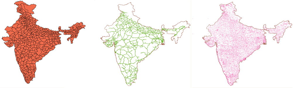
There are three kinds of topology: polygon, network (lines), and node (points). The illustration below shows the three types as they apply to an entire country: the division of land into districts, the network of railway lines, and the distribution of cities.
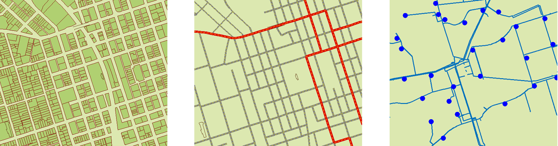
The following illustration gives further examples of the three types of topology on the scale of a single city: the parcel fabric, the street network, and the distribution of hydrants (blue circles).
It’s fairly obvious that a street network or a railway network can be a topology, but how can a collection of points be regarded as a topology? The answer to this question is that topological relationships are not confined to connectivity, but also include adjacency and relative position. In simple terms, the topology knows where the points are, which means that you can use a node topology, together with a polygon topology, to find out which cities are within a particular district, or which hydrants are within a particular parcel.
Before you create a topology, it is a good idea to make sure that your data is “clean,” that is, free from duplicate nodes, overlapping and intersecting line segments, and so on. The process of creating a topology may not work if these kind of errors are found. For more information, see Clean up duplicates, gaps, and other accuracy problems in DWG files.
You will see how to use topologies to make an overlay analysis in a later skill (see Find which lines are within a particular polygon (overlay analysis)). Before you can do any analysis, however, you need to create your topologies. This demonstration shows how to create a network topology of the Indian railway system. The process for creating a polygon or node topology is very similar and uses the same sequence of dialog boxes.