


The different kinds of layers in AutoCAD Map 3D can be a little confusing at first. The generic term “layer,” by itself, refers to the layers in the Display Manager. “AutoCAD layers” refers to the classic layers of DWG objects which appear in the Layer Properties Manager. You may also see the term “drawing layers.” These are layers which appear in the Display Manager, but which have been created from AutoCAD layers, or from other elements in the DWG, such as queries or topologies. There are several good reasons why you might want to create drawing layers from the objects in your DWG:
- Control all layers in the map directly from the Display Manager.
- Style the DWG objects using the Display Manager.
- Set scale ranges for the DWG objects so they are visible only when you zoom in.
- Create themes from the DWG objects.
Take, for example, the map in the illustration below. This map is composed of layers made from features and from AutoCAD layers.
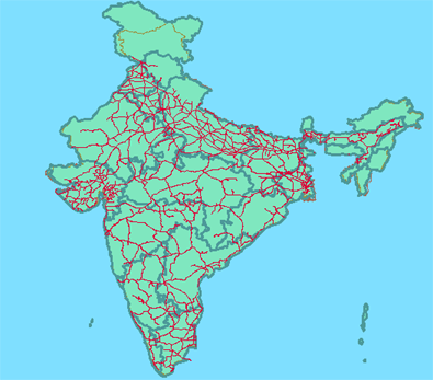
At the bottom of the Display Manager, whenever you start AutoCAD Map 3D, you see a default layer labeled “Map Base.” What does this layer do? Its purpose is to serve as a container for all the visible AutoCAD layers. Therefore, if you turn it off, none of the AutoCAD layers in the Layer Properties Manager will be displayed. This does not affect the AutoCAD layers in any way, that is, it does not turn the light bulb off or freeze them, it simply means that they are not displayed in the map. However, if you make a drawing layer from one of the AutoCAD layers, it gets its own layer in the Display Manager and is no longer included in the Map Base layer. This will be clearer if we look at an example.
In the illustration above, the Map Base displays three AutoCAD layers: the blue rectangle, the coastline (brown polyline), and the railway network (red polylines). The green state boundaries are in a feature layer.
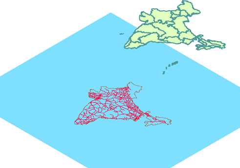
If we now create a drawing layer for the railway network, the structure of the map looks like this:
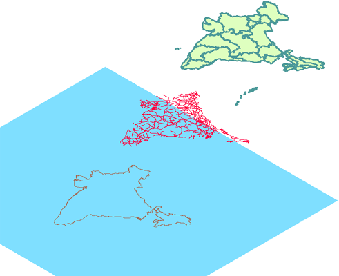
The railway lines have been placed on their own layer and are no longer under the control of the Map Base layer. The visibility and styling of these polylines can now be handled separately in the Display Manager.
The animation below demonstrates the main points of the preceding discussion. It starts with a review of the visible AutoCAD layers in the Layer Properties Manager, then shows how to create a drawing layer for one of them (the railway lines). It concludes by showing the effect of creating the drawing layer in the Display Manager.
Show me how to include an AutoCAD layer in the Display Manager