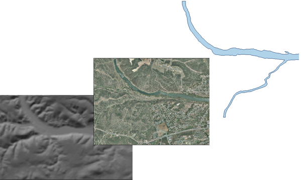
Vector layers are layers that contain features, which can be lines, points, or polygons. Raster layers contain images such as photographs or scanned topographic maps. Draping means overlaying layers on a surface so that they follow the terrain. Of course, you only see this effect in a 3D view. The illustration below shows a DEM surface on the left. The photo, in the center, is a raster layer and the flood zone feature, on the right, is a vector layer. You can drape both these types of layers on top of the surface.

In AutoCAD Map 3D, draping happens automatically when you switch to 3D mode. Any layers that are visible and which are above a surface in the draw order are draped on the surface. You don’t have to do anything to make the layers conform to the terrain. It is assumed that when you switch to 3D, you want to see everything in 3D. The layers which are draped are also trimmed to the edges of the surface. Again, the assumption is that when you go to a 3D view, you do not want to see any features that are not supported by an underlying surface.

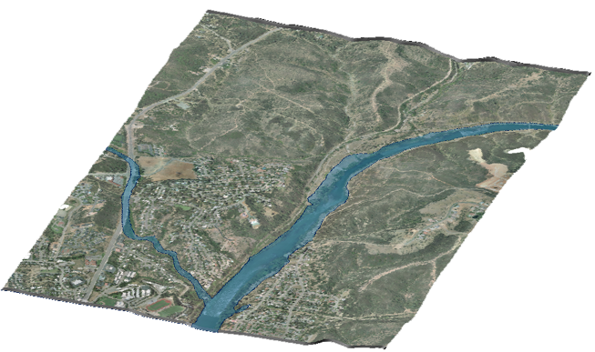
This animation shows the result of draping a vector and a raster layer on a surface. In the demonstration, we use named views to go quickly to a 3D view that has already been defined. However, you would normally use the 3D navigation tools first to set your 3D view. (See View a site in 3D for a demonstration of some of these tools.)
Show me how to drape layers on a surface


